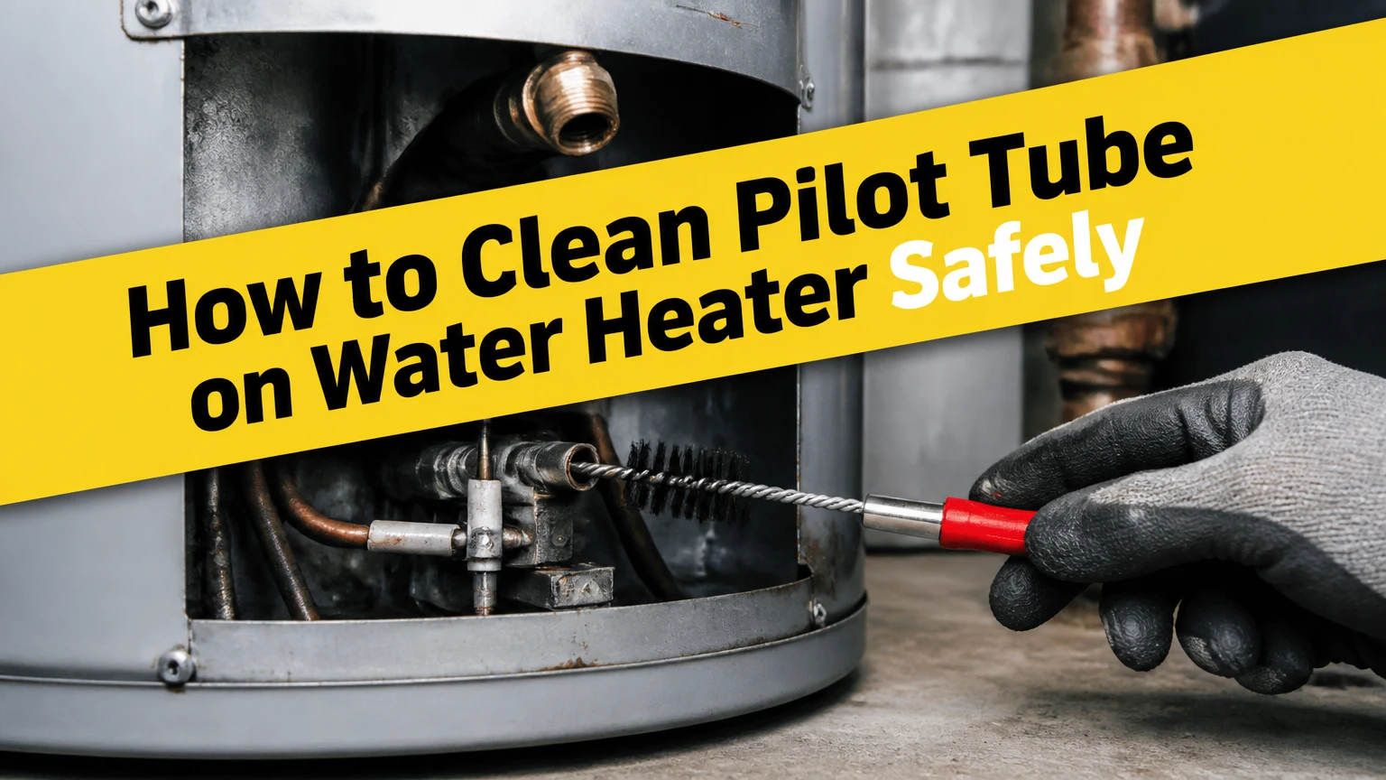
To clean a pilot tube on a gas water heater, shut off the gas, let the burner assembly cool, remove accessible dust with a soft brush or compressed air, and inspect the pilot orifice and flame. Do not force a needle, drill bit, or wire through the orifice, and do not open a sealed combustion chamber unless the manufacturer permits it.
Key Facts at a Glance
The pilot tube carries low-pressure gas from the control valve to the pilot burner; the tiny orifice meters the gas.
Most weak pilot flames come from a dirty orifice, blocked air openings, poor thermocouple positioning, or a failing gas-control component.
A pilot orifice is precision-sized. A needle or drill can enlarge it and create an unsafe flame.
Typical external cleaning takes 15-30 minutes; removing and servicing a burner assembly commonly takes 45-90 minutes.
Gas odor, a damaged burner-door gasket, corrosion, kinked tubing, or a carbon monoxide alarm requires immediate escalation.
The appliance installation and service manual controls the procedure for that specific water heater.
What Is the Pilot Tube on a Water Heater?
The pilot tube is the narrow metal line that carries gas from the water heater’s gas control valve to the pilot burner. The pilot tube is not the flame outlet itself. Gas travels through the tube, passes through a precision pilot orifice, mixes with combustion air, and exits at the pilot burner hood.
A typical tube has a 1/8-inch or 1/4-inch outside diameter, but diameter alone does not identify a replacement part. Copper, aluminum, and steel tubing can appear similar while using different flare fittings, lengths, or burner assemblies. Bradford White, A. O. Smith, Rheem, and State models may use different service procedures even when their visible pilot systems look alike.
The pilot orifice usually sits at the burner end of the tube or inside the pilot burner assembly. The thermocouple or thermopile sits beside the flame and confirms that combustion is present. Confusing these components leads to incorrect cleaning, especially when a homeowner cleans the thermocouple but leaves a restricted orifice untouched.
How Does a Pilot System Work?
A gas water heater pilot system uses gas flow, combustion air, ignition, and a flame-safety sensor in sequence. The control valve sends gas through the pilot tube, the orifice meters that gas, the pilot burner ignites it, and the flame heats the thermocouple or thermopile so the safety valve can remain open.
A standard thermocouple commonly produces approximately 25-30 millivolts when properly heated, while a thermopile produces a substantially higher signal, often several hundred millivolts. The exact output depends on the component and manufacturer test conditions, so a voltage reading should be compared with the appliance service manual rather than a generic internet threshold.
The pilot flame also needs primary air. Lint, pet hair, dust, spider webs, and rust flakes can block air openings around the pilot burner even when the pilot tube itself is clear. A dirty sensor can create the same symptom as a clogged tube because the flame no longer heats the sensor reliably.
Which Water Heater System Do You Have?
Identify the ignition system before cleaning because the access procedure and hazards differ.
| System type | Pilot behavior | Common components | Cleaning limit |
|---|---|---|---|
| Standing pilot | Flame remains lit continuously | Pilot tube, orifice, thermocouple | External dust cleaning is often accessible |
| Intermittent pilot | Igniter lights pilot only during a heat call | Igniter, flame sensor, pilot assembly | Follow model-specific ignition procedure |
| Direct ignition | Main burner ignites without a standing pilot | Igniter, burner, flame sensor | No conventional pilot tube to clean |
| FVIR sealed combustion | Burner operates inside a sealed chamber | Burner door, gasket, pilot assembly | Do not open without manual instructions |
| Power-vented gas | Electronic ignition and powered exhaust | Igniter, control board, pressure switch | Electrical and venting diagnosis may be required |
A standing-pilot water heater is the most likely match for the phrase “pilot tube.” Many newer units use electronic ignition, and some have no continuously burning pilot at all. A model number on the rating plate is more reliable than the appearance of the access door.
What Should You Prepare Before Cleaning?
Prepare the correct manual, a flashlight, safety glasses, work gloves, a soft nylon brush, and a can of clean compressed air. Typical consumable cost is $5-$15, but a replacement pilot assembly can cost substantially more, commonly $30-$150 depending on the manufacturer and system.
Before You Start
Time: 15-30 minutes for external cleaning; 45-90 minutes for approved burner-tray removal.
Difficulty: Low for external cleaning; moderate to high for gas-fitting disconnection.
Gas control: Identify the appliance gas shutoff valve and the upstream manual shutoff valve.
Tools: Flashlight, nylon brush, compressed air, adjustable wrench or manufacturer-specified wrench, and leak-detection solution.
Prerequisite: Locate the lighting and service instructions on the tank jacket or in the manual.
Do not proceed: If you smell gas, see damaged tubing, cannot identify the shutoff, or have an FVIR door gasket problem.
| Cleaning approach | Typical time | Typical material cost | Suitable situation |
|---|---|---|---|
| Brush and air through access opening | 15-30 minutes | $0-$15 | Dust or lint around an accessible pilot |
| Remove pilot burner only | 30-60 minutes | $5-$25 | Manual explicitly permits component removal |
| Replace pilot assembly | 45-90 minutes | $30-$150 | Kinked, corroded, or damaged tube |
| Professional diagnosis | 30-90 minutes | $150-$300 labor typical | Gas-valve, venting, gasket, or combustion fault |
How to Clean the Pilot Tube on a Water Heater
The safest general procedure is external cleaning first, followed by inspection and a manufacturer-approved internal service only when necessary. The critical success factor is preserving the pilot orifice size, tubing shape, burner-door seal, and original connection arrangement.
Step 1: Turn Off Gas and Electrical Power
Turn the gas-control knob to OFF, then close the manual gas shutoff on the rigid supply pipe. Turn off the circuit breaker or service switch on power-vented and electronically controlled units, because the ignition system and exhaust fan may still operate.
Do not rely on the control knob alone when disconnecting a gas fitting. Leave the water supply and water piping intact unless the service manual specifically requires another shutdown.
Success checkpoint: The gas-control display or knob indicates OFF, the manual shutoff handle is perpendicular to the pipe where that convention applies, and the burner cannot initiate ignition.
Common mistake: Turning off only the thermostat or electrical switch while leaving the gas supply available.
Step 2: Wait for the Burner and Chamber to Cool
Wait at least 15-20 minutes after shutdown, and use a longer cooling period if the burner has recently operated for an extended cycle. Metal burner parts, the flue area, and nearby tank surfaces can remain hot after the visible flame disappears.
Keep combustible cleaners, paper towels, and aerosol products away from the heater. Never use a flame to check whether a component is hot or whether gas is present.
Success checkpoint: The access area is cool enough to touch briefly with a gloved hand, and no combustion sound or exhaust operation remains.
Common mistake: Starting immediately after the pilot goes out, when heat can damage gloves or ignite debris.
Step 3: Identify the Pilot Assembly and Access Method
Remove only the outer access cover unless the appliance manual directs you to remove an inner panel. Locate the thin pilot tube, the thicker main-burner tube, the thermocouple, and the pilot burner near the bottom of the tank.
Photograph the connections before moving anything. Some assemblies use a combined manifold connection, while others route separate fittings into the gas control valve. FVIR appliances may use a sealed burner door with a gasket that must remain correctly aligned.
Success checkpoint: You can identify the pilot tube without confusing it with the thermocouple or main burner tube, and you know whether the chamber is sealed.
Common mistake: Removing a sealed combustion door because it resembles a removable inspection cover.
Step 4: Clean Dust and Lint Without Disconnecting Gas Lines
Use a soft nylon brush to loosen lint, dust, spider webs, and loose rust from the pilot burner hood, nearby air openings, and the access area. Direct short bursts of compressed air across the assembly rather than forcing debris deeper into the burner.
Keep the nozzle several inches away and use clean, dry air. Do not spray flammable solvent, carburetor cleaner, penetrating oil, or aerosol contact cleaner into the pilot assembly.
Low-contact cleaning is appropriate when the flame problem began after dust accumulation and the pilot tube is not visibly kinked or corroded. It is not a substitute for replacing a damaged assembly or diagnosing a gas-control failure.
Success checkpoint: Air openings are visibly clear, loose debris is removed, and the pilot hood remains aligned with the sensor.
Common mistake: Using a stiff steel brush that bends the hood or deposits metal fragments near the orifice.
Step 5: Inspect the Tube, Fittings, Orifice, and Sensor
Inspect the pilot tube along its entire visible length. Look for a crushed section, sharp bend, green copper corrosion, white oxidation, loose flare nut, abrasion, or evidence that the tube has contacted the burner flame.
Inspect the pilot burner and orifice without enlarging the opening. A pilot orifice is a calibrated gas-metering component, not a general-purpose hole that can be reamed to improve flow. Manufacturer service literature commonly specifies cleaning with approved compressed air or replacement rather than improvising with a needle.
Clean a lightly oxidized thermocouple tip with a fine abrasive pad only if the manual allows it, using gentle strokes that remove surface residue without thinning the sensor. Do not coat the tip with oil or compound.
Success checkpoint: The tube has no kink, the orifice is present and seated, the sensor is positioned in the pilot flame path, and no fitting appears damaged.
Common mistake: Treating the symptom by scraping the thermocouple while ignoring a blocked pilot burner air inlet.
Step 6: Do Not Force a Needle Through the Orifice
Do not insert a sewing needle, drill bit, safety pin, or improvised guitar string into the pilot orifice. These tools can enlarge or distort the opening, change the gas flow, and produce a lazy yellow flame with increased soot and carbon monoxide risk.
If compressed air does not clear a suspected restriction, follow the service manual’s approved orifice-cleaning method. In many assemblies, replacing the correct orifice or the complete pilot burner is safer than attempting to recover a contaminated precision opening.
A professional should handle an orifice that is stuck, corroded, inaccessible, or integrated into a sealed burner assembly. The cost of a replacement part is usually lower than the consequences of an altered gas-air mixture.
Success checkpoint: The orifice remains undamaged and the pilot burner has not been drilled, reamed, or chemically flooded.
Common mistake: Assuming a larger opening creates a stronger, healthier pilot. Correct pilot performance depends on the specified gas flow and air mixture.
Step 7: Reassemble Only as the Manual Specifies
If the manual permits removal, reinstall the pilot tube and other fittings by hand first. Hand-threading helps prevent cross-threading. Tighten with the specified wrench method, but do not use excessive force on soft tubing or small flare fittings.
Do not bend a copper or aluminum pilot tube to make a misaligned connection fit. A kinked tube requires replacement, and a stressed flare can leak even when the nut feels tight.
Replace a burner-door gasket if it is torn, compressed unevenly, missing, or displaced. A sealed combustion door is part of the safety design, not a cosmetic cover.
Success checkpoint: Every fitting starts smoothly, the tube follows its original route, and the burner door closes with the gasket evenly seated.
Common mistake: Reusing a damaged gasket or tightening a flare nut until the tubing twists.
Step 8: Leak-Test Every Disturbed Gas Connection
Open the manual gas shutoff slowly. Apply an approved noncorrosive leak-detection solution, or a small amount of dish soap mixed with water, to every connection that was disturbed, including both ends of the pilot tube.
Watch for growing bubbles for at least 30 seconds. A single stationary bubble can come from application, but expanding bubbles indicate escaping gas.
Success checkpoint: No connection produces expanding bubbles, and the area has no gas odor.
Common mistake: Checking only the gas-control-valve connection while ignoring the burner-side fitting.
If bubbles grow or gas odor appears, close the manual shutoff, avoid switches and flames, ventilate only if safe, leave the area, and contact the gas utility or a qualified technician. Never relight an appliance with a suspected leak.
Step 9: Relight and Verify the Pilot Flame
Follow the exact lighting label on the water heater. Standing-pilot models commonly require holding the control in a pilot position while pressing an igniter, but ignition timing and hold duration vary by control valve.
A healthy pilot is generally blue and stable, with the flame contacting the specified portion of the thermocouple or flame sensor. A small yellow tip can occur on some designs, but a mostly yellow, floating, noisy, or lifting flame is not a successful result.
Success checkpoint: The pilot remains lit after the manual’s hold period, the flame consistently heats the sensor, and the main burner ignites without delayed ignition or rollout.
Common mistake: Increasing the gas-control setting to compensate for a restricted orifice. Temperature settings do not correct a pilot-air or pilot-flow problem.
What Should the Flame Look Like?
A properly adjusted pilot flame is stable, predominantly blue, and directed at the manufacturer-specified sensor area. Flame color alone cannot prove safe operation, because room lighting, dust, gas pressure, burner design, and combustion-air conditions affect appearance.
| Flame observation | Likely area to inspect | Correct response |
|---|---|---|
| Small blue flame | Restricted orifice or tube; low gas pressure | Clean by approved method, then arrange diagnosis |
| Mostly yellow flame | Blocked air opening, soot, incorrect orifice | Shut down if persistent and call a technician |
| Flame lifts from hood | Excess gas, draft, wrong orifice | Do not operate until diagnosed |
| Flame blows out | Downdraft, blocked vent, weak flow | Check for venting and airflow service |
| Flame misses sensor | Misaligned pilot hood or thermocouple | Correct alignment only if manual permits |
| No pilot gas | Gas shutoff, control valve, safety circuit | Do not bypass the safety system |
A combustion analyzer is the appropriate tool for verifying combustion performance when the flame remains abnormal. Visual inspection cannot measure carbon monoxide or confirm correct gas pressure.
Can You Clean the Pilot Tube Without Removing It?
You can clean visible dust and lint without removing the pilot tube, but you cannot reliably clear an internal restriction or service a hidden orifice through an access opening. External brush-and-air cleaning is the appropriate first step for an accessible standing-pilot assembly with no damaged parts.
This low-contact method reduces the chance of cross-threading fittings, bending tubing, or disturbing a burner-door seal. It also has a firm limitation: if the pilot remains weak after external cleaning, repeated blowing will not repair a failing thermocouple, blocked internal orifice, low inlet pressure, or defective gas control.
A novice should stop at external cleaning. Disconnecting a gas line is a separate repair task, not an automatic part of routine maintenance.
Should You Clean or Replace the Pilot Assembly?
Replace the pilot assembly when the tube is kinked, deeply corroded, heat-damaged, or incompatible with the original fittings. Cleaning is reasonable when the assembly is structurally sound and the problem is limited to removable dust or surface residue.
| Condition | Clean and reuse? | Replace or escalate? | Reason |
|---|---|---|---|
| Dust around pilot hood | Yes | No | External contamination is removable |
| Surface soot on sensor | Usually | No, if sensor remains intact | Light residue may be removed |
| Kinked pilot tube | No | Replace assembly | Flow restriction remains permanent |
| Green, pitted copper | No | Replace assembly | Corrosion can cause leakage |
| Blocked integrated orifice | Only per manual | Replace or service | Improvised reaming changes calibration |
| Torn FVIR gasket | No | Replace gasket and inspect | Sealed combustion may be compromised |
| Pilot will not stay lit | Not by itself | Diagnose sensor or valve | Tube cleaning may not address fault |
Universal pilot kits are not automatically interchangeable. Match the manufacturer, model, fuel type, gas pressure, connection style, burner configuration, and sensor arrangement. Natural-gas and propane components must not be substituted without explicit manufacturer approval.
Why Does the Pilot Still Fail After Cleaning?
A pilot that still fails after cleaning usually has a sensor, airflow, gas-pressure, venting, or control-valve problem rather than a dirty tube alone. The diagnostic clue is what happens after ignition: immediate extinction, delayed extinction, weak flame, or failure to produce gas points to different components.
The Pilot Lights but Goes Out
A pilot that goes out when the control button is released commonly has a weak or misdirected flame, a poorly positioned thermocouple, a loose thermocouple connection, or a failed thermocouple. Confirm sensor placement and the manual’s hold time before replacing parts.
Do not bypass the thermocouple, thermopile, ECO, or other flame-safety device. A bypass defeats the mechanism intended to shut off gas when combustion is absent.
The Flame Is Yellow or Sooty
A yellow or sooty pilot can indicate blocked primary-air openings, an incorrect or damaged orifice, inadequate combustion air, or a venting problem. Persistent yellow flame should be treated as a combustion fault, not as a cosmetic issue.
Stop using the heater if soot accumulates around the burner, viewport, or draft hood. A carbon monoxide alarm is an emergency warning, and occupants should leave the area and contact emergency services or the gas utility according to local guidance.
The Pilot Has No Gas Flow
No gas at the pilot may result from a closed manual valve, air in a recently serviced line, a tripped safety control, failed ignition control, inadequate inlet pressure, or a defective gas valve. A homeowner should not remove a gas valve or defeat an energy cutoff.
A qualified technician can measure inlet and manifold pressure, test the thermocouple or thermopile, inspect the vent, and verify the control valve using the manufacturer’s service procedure.
The Pilot Goes Out During Wind or Burner Operation
Wind-related extinction can indicate downdraft, vent obstruction, inadequate combustion air, a missing draft component, or an installation problem. Cleaning the pilot orifice cannot correct unsafe venting.
Check that external vents are not blocked by snow, nests, leaves, or construction debris, but do not disassemble vent components unless qualified. Power-vented units may also shut down because of a pressure-switch or exhaust-fan fault.
What Are the Most Common Cleaning Mistakes?
The most damaging mistakes alter the gas system or bypass safety controls rather than failing to remove enough dust.
- Reaming the orifice: A needle or drill changes the calibrated opening. Replace the part instead.
- Bending soft tubing: A tight bend can restrict pilot flow and create a future leak at the flare.
- Skipping the leak test: A connection can leak without producing an obvious odor immediately.
- Opening an FVIR chamber casually: A displaced gasket can change sealed combustion behavior.
- Using flammable aerosol cleaner: Vapors can ignite during relighting.
- Replacing only the thermocouple repeatedly: The real fault may be the pilot flame, gas pressure, venting, or control valve.
A practitioner rule is to photograph every connection before disassembly and compare the final tubing route with the original image. Another is to replace a visibly heat-discolored pilot tube rather than attempting to polish it back into service.
When Should You Call a Professional?
Call a licensed gas-appliance technician when the heater has a gas odor, abnormal flame, carbon buildup, damaged tubing, a failed leak test, a sealed burner-door problem, or a pilot that will not remain lit after basic external cleaning. Professional service is also appropriate when the appliance is under warranty or the service manual requires pressure or combustion testing.
Stop immediately if you cannot identify the gas shutoff, cannot remove a fitting without force, find a cracked viewport, hear hissing, or see soot outside the combustion chamber. The American Gas Association and appliance manufacturers consistently place leak prevention, combustion-air supply, venting, and flame-safety operation ahead of homeowner component cleaning.
Do not use a water heater with a suspected carbon monoxide problem. Install carbon monoxide alarms according to local code and the alarm manufacturer’s instructions, but remember that an alarm does not replace appliance service.
How Much Time and Money Does Cleaning Take?
External pilot-area cleaning typically takes 15-30 minutes and costs $0-$15 when basic household tools are available. Approved burner-assembly service commonly takes 45-90 minutes, while professional diagnosis often costs $150-$300 in labor before parts, with local rates and access difficulty causing substantial variation.
| Service outcome | Typical labor time | Typical parts or materials | Practical decision |
|---|---|---|---|
| External dust removal | 15-30 minutes | $0-$15 | Reasonable first step |
| Thermocouple replacement | 30-60 minutes | $10-$40 | Match model and connection |
| Pilot assembly replacement | 45-90 minutes | $30-$150 | Use exact approved assembly |
| Gas-control diagnosis | 45-120 minutes | $150-$500+ parts possible | Professional service recommended |
| FVIR gasket or door repair | 45-120 minutes | $20-$100+ | Follow manufacturer procedure |
Routine cleaning is not automatically required every one or two years. Frequency depends on lint, pets, construction dust, combustion-air conditions, and the appliance design. Inspecting the burner area during annual home maintenance is more defensible than forcing a fixed cleaning interval on every model.
FAQ
Can I use compressed air to clean a water heater pilot?
Yes, compressed air can remove loose dust and lint from an accessible pilot burner and its air openings. Use short, controlled bursts and keep the nozzle away from delicate components. Compressed air cannot repair a kinked tube, defective thermocouple, blocked internal passage, incorrect gas pressure, or failing control valve.
Is a thermocouple the same as a pilot tube?
No. The pilot tube is a gas-carrying metal line, while the thermocouple is a temperature sensor that generates a small electrical signal when heated. The pilot burner produces the flame, the pilot orifice meters gas, and the thermocouple confirms flame presence to the safety control.
How often should a gas water heater pilot be cleaned?
Inspect the pilot area annually and clean visible lint or dust whenever accumulation appears. A fixed one- or two-year cleaning interval does not suit every water heater because indoor dust, pets, combustion-air openings, and burner design vary. Follow the manufacturer’s maintenance schedule when one is provided.
Can a dirty pilot tube cause carbon monoxide?
A restricted or damaged pilot system can contribute to abnormal combustion, but carbon monoxide can also result from poor combustion air, venting defects, incorrect gas pressure, or a damaged burner. A yellow or sooty flame requires diagnosis. Never use flame color as the only carbon monoxide safety test.
Why does the pilot go out when the main burner starts?
The main burner can expose a weak pilot to drafts, reveal inadequate combustion air, or create a venting problem. A dirty pilot may contribute, but the same symptom can come from a misaligned sensor, blocked vent, pressure issue, or defective gas-control system. Stop operation if rollout or soot appears.
Is a universal pilot assembly safe to install?
A universal assembly is safe only when the manufacturer or a qualified technician confirms compatibility with the exact heater, fuel, gas pressure, fittings, burner, sensor, and sealed-combustion design. Similar-looking parts can have different orifice sizes. An exact factory-approved assembly is the safer choice when the original tube is damaged.
The Bottom Line
Cleaning a pilot tube on a water heater should begin with gas shutoff, cooling, external brushing, and controlled compressed air. Do not enlarge the pilot orifice, bend soft tubing, open an FVIR chamber casually, or bypass a flame-safety device. If the pilot remains weak, yellow, unstable, or impossible to light after approved cleaning, replace the matched assembly or have a qualified technician diagnose the heater.