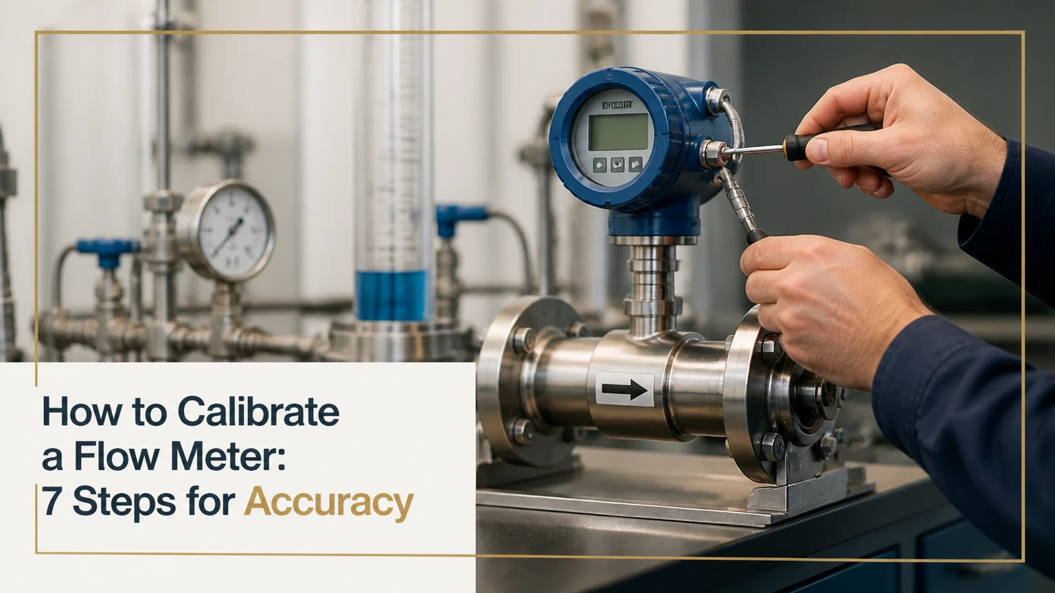
To calibrate a flow meter, compare the device under test with a traceable reference under stable, representative flow conditions, record the as-found error, adjust only when permitted, and verify the result at multiple flow points. A defensible calibration normally takes 2-5 hours in the field or 3-12 business days in a laboratory.
Key Facts at a Glance
Calibration compares a flow meter with a higher-accuracy reference; verification checks whether the existing reading meets a limit.
A calibration test should use the same fluid, temperature range, pressure range, and approximate flow profile as the installation.
Typical industrial testing uses at least three points, often 25%, 50%, 75%, and 100% of the selected operating range.
A 4:1 test uncertainty ratio is a common planning target, but the required ratio depends on the procedure, tolerance, and regulation.
Liquid systems must remain full and free of entrained air because gas pockets can produce large volume errors.
Every adjustment requires as-found and as-left records, reference-standard identification, environmental data, and acceptance criteria.
What Does Flow Meter Calibration Measure?
Flow meter calibration measures the difference between a meter’s indicated flow and a traceable reference value. The reference may determine mass with a weighing system, volume with a prover, or flow by comparison with a calibrated master meter.
Calibration is not automatically the same as adjustment. A technician first records the meter’s original performance, called the as-found condition. The technician then decides whether cleaning, configuration changes, repair, or electronic adjustment is justified. A second test records the as-left condition.
The basic error calculation is:
[ \text{Percent Error}= \frac{\text{Meter Indication}-\text{Reference Value}} {\text{Reference Value}}\times100 ]
For example, if a reference measures 1,000 L and the meter registers 1,006 L, the error is:
[ \frac{1006-1000}{1000}\times100=+0.6% ]
The sign matters. Positive error means the meter reads high; negative error means it reads low. A calibration certificate should also state whether the reported result is corrected, uncorrected, or adjusted.
Before You Start: Equipment, Conditions, and Safety
A basic liquid calibration requires the meter manual, a suitable reference, a stable pump and control valve, temperature and pressure instruments, a timer or data logger, and the correct fittings and gaskets. The test fluid must match the meter’s material compatibility and operating requirements.
| Requirement | Typical specification | Why it matters |
|---|---|---|
| Reference uncertainty | 0.025%-0.25% of reading | Supports the required test tolerance |
| Test points | 25%, 50%, 75%, 100% of range | Reveals linearity and range-dependent error |
| Straight pipe | 5-20 nominal diameters upstream | Reduces swirl and profile distortion |
| Stabilization period | 5-30 minutes | Equalizes temperature and removes transients |
| Pressure stability | Within 1%-2% during a run | Prevents changing meter behavior |
| Repeat runs | 2-3 at each point | Separates repeatability from bias |
Use the manufacturer’s installation requirement instead of treating ten pipe diameters as universal. A magnetic meter, Coriolis meter, turbine meter, vortex meter, and ultrasonic meter respond differently to upstream disturbances.
Depressurize, drain, lock out, and verify the line before removing an installed meter. Hydrocarbon, steam, corrosive, toxic, and high-pressure services require a documented permit and competent personnel. A portable reference meter is not a substitute for process isolation.
How should the reference standard be selected?
Select a reference whose range covers every test point and whose uncertainty is smaller than the meter tolerance. NIST describes metrological traceability as an “unbroken chain of calibrations,” with each link contributing to measurement uncertainty. The certificate must identify the reference, calibration date, conditions, uncertainty, and traceability statement.
The often-cited 4:1 TUR, or test uncertainty ratio, means the reference system is intended to be about four times more accurate than the tolerance being tested. It is a useful design target, not a universal law. If a meter has a permitted error of ±0.5%, a reference uncertainty near 0.125% or lower is a sensible target, subject to the governing procedure.
A reference with a 4:1 ratio can still produce a poor decision if installation effects, temperature changes, timing errors, or fluid-property differences dominate the test. The complete measurement uncertainty budget matters more than one ratio.
How to Calibrate a Flow Meter in Seven Steps
The following wet calibration procedure applies mainly to liquid meters and can be adapted for gas or steam only after changing the reference method, pressure controls, and property corrections. A complete multi-point test typically takes 2-5 hours on an accessible process line.
Step 1: Define the Range and Acceptance Criteria
Write the test range, fluid, units, accuracy limit, repeatability limit, flow points, and adjustment authority before connecting equipment. Use the operating range rather than automatically testing the transmitter’s full nameplate range.
For a water meter normally operating from 20 to 80 L/min, sensible test points may be 20, 40, 60, and 80 L/min. A meter used for custody transfer may require a contract, legal-metrology, or company procedure with tighter points and proving requirements.
Record:
- Meter manufacturer, model, serial number, line size, and firmware
- Flow direction and output type, such as pulse, 4-20 mA, frequency, or digital total
- Reference serial number and certificate expiry date
- Fluid density, viscosity, conductivity, temperature, and pressure
- Required tolerance, uncertainty, and repeatability limit
Success checkpoint: The technician can state exactly what result passes before testing begins.
Common mistake: Using the meter’s maximum flow as the only calibration point. Low-flow zero instability and mid-range linearity problems then remain hidden.
Step 2: Install the Reference and Stabilize the Loop
Install the reference and meter in series, or route the same controlled volume through both instruments. Confirm correct flow direction, full-bore connections, leak-free joints, grounding, and adequate upstream and downstream piping.
Use a control valve downstream of the meters where possible. Downstream throttling maintains back-pressure and reduces flashing or cavitation. A partially filled pipe invalidates most liquid-meter comparisons.
Start the pump slowly. Open vents at high points until no air remains, then circulate fluid until the meter body, reference, and test fluid approach the same temperature. Stabilization commonly takes 5-30 minutes, although large process loops may require longer.
Success checkpoint: Pressure, temperature, flow, and output remain stable for the planned run duration.
Common mistake: Controlling flow with a valve immediately upstream of the meter, which can create turbulence and pressure instability.
Step 3: Confirm Zero and Process Health
Stop flow while keeping the liquid meter completely full and the line pressure within the manufacturer’s zeroing range. Observe the output for at least 30-60 seconds. A changing zero usually indicates trapped gas, vibration, electrical interference, unstable pressure, or an empty measurement tube.
Do not zero a meter simply because its display differs from the reference during flowing conditions. Zeroing corrects the no-flow baseline; it does not correct a scale factor, damaged sensor, incorrect pipe size, or wrong fluid-property configuration.
For electromagnetic meters, check grounding electrodes, grounding rings, and conductivity. For Coriolis meters, confirm that the tube is full and free from two-phase flow. For ultrasonic meters, inspect signal strength and sound-path quality.
Success checkpoint: The no-flow output remains within the manufacturer’s stated zero stability limit.
Common mistake: Zeroing with an empty pipe. The resulting baseline can be wrong when the pipe is later filled.
Step 4: Record the As-Found Performance
Run the meter at each defined point without changing its calibration settings. Allow the flow to stabilize, then collect enough volume or time for the reference uncertainty and pulse resolution to become small compared with the acceptance limit.
A typical field run lasts 30-120 seconds per point. A low-flow pulse meter may need a longer run because one pulse represents a larger fraction of the total measurement. Record the reference value, meter indication, elapsed time, temperature, pressure, density, total pulses, and calculated error.
Repeat at least one point, preferably the mid-range point, to assess repeatability. If consecutive runs differ by more than the procedure allows, stop adjusting and investigate the process.
Success checkpoint: As-found results show a stable error pattern, such as a constant bias, a linear span error, or a flow-dependent curve.
Common mistake: Adjusting before collecting as-found data. That removes evidence of drift and makes maintenance decisions harder to defend.
Step 5: Choose the Correct Reference Method
Choose gravimetric, volumetric, or master-meter calibration according to the fluid, required uncertainty, meter size, and field constraints.
| Method | Reference quantity | Typical application | Main limitation |
|---|---|---|---|
| Gravimetric | Mass collected on a calibrated scale | Water, chemicals, Coriolis checks | Requires stable collection and density correction |
| Volumetric | Certified vessel or prover volume | Small liquid meters, utilities | Meniscus, temperature, and reading errors |
| Master meter | Calibrated meter in series | Field lines and large pipes | Shares installation effects with the DUT |
| Piston prover | Displaced calibrated volume | Petroleum and custody transfer | High cost and procedural complexity |
| Bell or sonic nozzle | Gas volume or mass relationship | Air and low-pressure gas | Limited pressure and flow range |
Gravimetric testing calculates mass flow as mass divided by time. If the meter displays volume, convert mass to volume using the fluid density at the relevant temperature. A density assumption that ignores temperature can introduce a material error in liquids with high expansion coefficients.
A master meter is often the practical field choice, but a clamp-on ultrasonic instrument should not automatically be treated as a laboratory reference. Wall thickness, pipe lining, sound velocity, transducer placement, temperature, and flow profile can affect its result.
Success checkpoint: The selected method has a documented uncertainty appropriate to the acceptance limit.
Common mistake: Calibrating a heavy oil meter with room-temperature water and assuming the result transfers unchanged. Reynolds number, viscosity, density, and meter response can differ substantially.
Step 6: Adjust the Meter Only After Diagnosing the Error
Adjust the parameter that matches the observed error pattern. A constant offset may indicate zero, while a proportional error usually indicates span, K-factor, density, pulse scaling, or an incorrect engineering range.
For pulse-output instruments, the K-factor represents pulses per unit volume. If a meter produces 10,000 pulses while the reference measures 100 L, the observed K-factor is:
[ K=\frac{10,000}{100}=100\text{ pulses/L} ]
If the configured value is 98 pulses/L, the totalizer will calculate too much volume for the same pulse count. Change the K-factor only after confirming the output wiring, pulse width, scaling units, and totalizer configuration.
| Error pattern | Likely cause | First check | Typical correction |
|---|---|---|---|
| +0.5% at every point | Scale or K-factor bias | Pulse count and units | Correct span or K-factor |
| 0% at 50%, +2% at 10% | Low-flow sensitivity | Minimum operating flow | Clean, repair, or change range |
| Random ±1% runs | Unstable process | Pressure and air content | Increase back-pressure, purge air |
| Zero shifts after filling | Gas or grounding problem | Full pipe and zero signal | Remove gas or correct grounding |
| Error rises with temperature | Property compensation | Fluid temperature input | Correct density or temperature setup |
| Only digital total is wrong | Integration scaling | PLC/DCS multiplier | Correct receiving-system scale |
Never mask mechanical damage with an electronic correction. Turbine bearing wear, fouling, electrode coating, cracked liners, transducer damage, or sensor misalignment requires inspection or repair.
Success checkpoint: The adjustment addresses a diagnosed error mechanism and remains within the manufacturer’s configuration limits.
Common mistake: Applying a single K-factor to a meter whose calibration curve is visibly nonlinear. A multi-point correction, repair, or reduced operating range may be necessary.
Step 7: Perform As-Left Verification and Issue the Record
Repeat every test point after adjustment, using the same fluid conditions and reference method. Compare the new results with the acceptance limits and the as-found data.
A valid calibration record includes:
- As-found and as-left readings
- Reference values, units, and conversion equations
- Flow, pressure, temperature, density, and conductivity where applicable
- Meter and reference identification
- Test dates, technician, procedure revision, and software or firmware version
- Calculated error, uncertainty, repeatability, and pass or fail decision
- Adjustment details, seal number, and next due date
An accredited laboratory should identify its accreditation scope, often under ISO/IEC 17025, rather than merely displaying the standard’s name. Accreditation does not make every measurement suitable for every process; the scope and uncertainty must match the application.
Success checkpoint: Every point passes the stated criteria, repeated points agree, and another technician could reproduce the calculation.
Common mistake: Issuing a certificate that lists only “calibrated” without uncertainty, conditions, reference identification, or as-found results.
Which Calibration Method Is Best?
The best method depends on the measured phase and the required decision. Gravimetric testing is usually strongest for high-accuracy liquid work, volumetric proving is efficient for smaller liquid meters, and master-meter comparison is often the least disruptive field option.
| Decision factor | Gravimetric | Volumetric | Master meter |
|---|---|---|---|
| Typical setup time | 1-2 days | 4-8 hours | 2-5 hours |
| Best fluid | Water and low-viscosity liquids | Clean liquids | Process-compatible liquids |
| Large-pipe practicality | Low above 100 mm | Medium above 100 mm | High above 100 mm |
| Main uncertainty source | Scale, timing, density | Volume, temperature, meniscus | Reference and installation profile |
| Field portability | Low | Medium | High |
| Typical cost | $1,000-$3,000 | $500-$2,000 | $500-$2,000 |
Gas and steam meters require special treatment. A liquid collection tank cannot calibrate a steam vortex meter, and a liquid master meter cannot establish gas accuracy. Gas testing may use a sonic nozzle, critical-flow venturi, bell prover, piston prover, or calibrated reference meter under controlled pressure and temperature.
How Do Meter Types Change the Procedure?
Meter technology changes the checks that matter most. A Coriolis meter needs stable density and a full tube, an electromagnetic meter needs conductive liquid and sound grounding, and an ultrasonic meter needs a suitable acoustic path and a developed flow profile.
| Meter type | Primary checks | Typical adjustment | Poor candidate for |
|---|---|---|---|
| Coriolis mass | Density, zero, two-phase flow | Zero and mass span | Entrained gas or severe vibration |
| Electromagnetic | Conductivity, grounding, liner | Zero and span | Hydrocarbons with low conductivity |
| Ultrasonic | Signal strength, sound velocity, profile | Path factor or setup | Heavy swirl and aerated liquid |
| Turbine | Bearing condition, pulse output | K-factor | Dirty liquid and pulsation |
| Vortex | Reynolds number, shedding signal | K-factor and range | Very low flow or vibration |
| Positive displacement | Wear, leakage, temperature | Meter factor | Abrasive solids without protection |
| Rotameter | Float, scale, density, viscosity | Usually none | High-precision custody transfer |
A rotameter is commonly verified by comparing float position with a known flow, but scale reading depends on fluid density and viscosity. A visual check cannot establish the same uncertainty as a timed gravimetric test.
Clamp-on ultrasonic verification is useful when line shutdown is expensive. It is less reliable when the pipe wall, lining, transducer spacing, fluid sound velocity, or flow profile is uncertain. Treat the result as a field verification unless the instrument and setup support the required uncertainty.
How Often Should a Flow Meter Be Calibrated?
A practical interval is 6-12 months for critical or regulated service, 12-24 months for stable general process service, and a shorter interval after repair, contamination, unexplained drift, or a process change. The correct interval comes from risk and historical data, not a universal calendar rule.
Shorten the interval when the meter affects custody transfer, chemical dosing, environmental reporting, product yield, or safety. Extend it only when repeated as-found results demonstrate stable performance and the quality system permits risk-based intervals.
A useful program reviews:
- Historical as-found error and repeatability
- Consequence of over-measurement or under-measurement
- Fluid cleanliness, pressure cycling, vibration, and temperature
- Manufacturer recommendations and regulatory requirements
- Whether the meter has been removed, repaired, rewired, or reconfigured
What Causes Calibration Failure?
Most failed calibration results come from installation or process conditions rather than a bad transmitter. Entrained gas, cavitation, pulsation, swirl, changing temperature, incorrect density, and poor grounding can all create repeatability problems that an electronic adjustment cannot solve.
Unstable or noisy readings
Check pump pulsation, control-valve position, cavitation, vibration, electrical shielding, and reference stability. Increase downstream back-pressure where safe, purge gas, install a pulsation damper, or move the test point away from a transient.
Constant positive or negative bias
Check K-factor units, totalizer scaling, meter range, calibration factor, fluid density, and flow direction. A constant bias often indicates configuration rather than sensor failure.
Zero will not stabilize
Keep the pipe full, remove air, stop nearby vibration, verify grounding, and allow pressure to settle. Electromagnetic meters can show unstable zero when grounding rings or reference electrodes are incorrectly installed.
Results differ by flow rate
Inspect upstream piping, fouling, bearing wear, low-flow operation, Reynolds number, and meter range selection. A meter that passes at 75% of range may still fail at 10% if its low-flow signal is weak.
Temperature changes the result
Record temperature at the meter and reference, then apply the correct density or volume correction. Volumetric flow and material dimensions can change with temperature, particularly in petroleum and chemical applications.
How Much Does Calibration Cost?
Typical calibration costs range from $150-$600 for a basic off-site laboratory check, $500-$2,000 for an on-site field comparison, and $500-$3,000 for high-accuracy accredited laboratory work. Large-bore meters, hazardous locations, specialized fluids, and custody-transfer documentation can increase the price.
| Service type | Typical price | Typical lead time | Suitable use |
|---|---|---|---|
| Basic laboratory check | $150-$600 | 3-7 business days | General liquid instruments |
| On-site master-meter test | $500-$2,000 | 2-5 hours per meter | Installed process lines |
| ISO/IEC 17025 laboratory | $500-$3,000 | 5-12 business days | Regulated or high-accuracy work |
| Large-bore field proving | $1,500-$6,000 | 1-3 days | Pipes above 150 mm |
| Gas or steam specialist test | $1,000-$5,000 | 1-4 weeks | Compressed gas and steam systems |
These are typical planning ranges, not universal prices. Ask whether the quote includes removal, shipping, cleaning, hazardous-area procedures, uncertainty calculations, certificate issuance, and adjustment.
Can You Calibrate a Flow Meter Yourself?
You can perform a useful in-house verification on a water meter with a calibrated tank or scale, a stable pump, a stopwatch or data logger, and a controlled flow. A hobbyist or maintenance technician can identify gross errors, but the result is not automatically traceable or acceptable for legal billing.
For a simple gravimetric check, collect a known quantity, measure the elapsed time, record temperature, and convert mass to volume using an appropriate density value. Repeat at several flow rates and calculate percentage error. The scale, vessel, timing method, and fluid condition determine the result’s uncertainty.
Do not use an improvised test for custody transfer, regulated emissions, pharmaceutical release, safety interlocks, or contractual billing. Those applications usually require a documented procedure, suitable reference, uncertainty statement, and qualified laboratory or service provider.
When Should You Use a Calibration Laboratory?
Use an accredited calibration laboratory when the meter supports custody transfer, regulated reporting, product release, or a dispute where independent evidence is needed. A laboratory is also preferable when the meter requires controlled temperature, high-pressure gas, specialized density measurement, or a prover unavailable at the site.
A field master-meter test is usually better when removing the instrument would interrupt production, damage process seals, or require a crane. The field result must still account for installation effects and reference uncertainty.
FAQ
Does calibration make a damaged flow meter accurate?
No. Calibration identifies measurement error and may correct configuration, but it cannot restore worn bearings, damaged liners, coated electrodes, cracked tubes, blocked impulse paths, or degraded ultrasonic transducers. Repair or replacement should precede final calibration when the as-found pattern indicates physical damage.
What is the difference between calibration and verification?
Calibration quantifies the relationship between a meter indication and a reference value, usually across several points. Verification checks whether the instrument currently meets a defined limit and may use fewer points. Verification is useful for routine health checks, while calibration produces a more complete measurement record.
Can I calibrate a flow meter without removing it?
Yes, if the process can accept a suitable master meter or reference system in series and the line provides safe, stable conditions. In-line comparison does not remove errors caused by poor straight runs, gas, pulsation, or unsuitable reference installation. A laboratory test may still be required for regulated service.
What accuracy should a calibration reference have?
Choose a reference with uncertainty small enough for the acceptance decision; a 4:1 TUR is a common starting rule. For a ±0.5% meter tolerance, a reference near ±0.125% is a reasonable target before considering temperature, timing, density, installation, and repeatability contributions.
Why does a flow meter read correctly at high flow but fail at low flow?
Low flow reduces signal strength and increases the relative effect of zero offset, pulse resolution, leakage, friction, and installation disturbance. Confirm the meter’s minimum operating flow, repeat the test with longer collection time, and check whether the selected range is too large.
What should a calibration certificate contain?
A certificate should identify the meter and reference, test method, traceability, environmental and process conditions, as-found and as-left readings, calculated errors, uncertainty, acceptance criteria, adjustments, technician, date, procedure revision, and next due date. A bare pass statement is inadequate for a defensible measurement record.
The Bottom Line
The safest way to calibrate a flow meter is to define the acceptance limit, use a traceable reference, stabilize the actual fluid conditions, record as-found performance, diagnose before adjusting, and complete multi-point as-left verification. Gravimetric, volumetric, and master-meter methods each have valid applications, but none compensates for air, cavitation, swirl, incorrect scaling, or an unsuitable reference. For custody transfer and regulated measurement, use a qualified provider whose uncertainty and documentation match the decision.