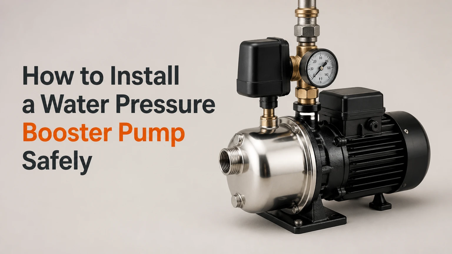
To install a water pressure booster pump, measure incoming pressure and flow, select a pump that matches the required demand, then plumb it after the water meter with isolation valves, unions, gauges, and approved backflow protection. Prime the pump before energizing it, verify electrical protection, and set the final pressure within local code and appliance limits.
Key Facts at a Glance
Typical residential water pressure is approximately 40-60 psi, while many plumbing codes treat 80 psi as the upper limit requiring pressure control.
A booster pump increases pressure and flow only when the incoming supply can provide enough water; it cannot create water that the utility, well, or service pipe cannot deliver.
A whole-house booster normally belongs on the cold-water main after the meter and before branch lines, subject to utility and local plumbing approval.
A bypass loop with two isolation valves, one bypass valve, and union fittings allows pump removal without disabling the entire house.
A centrifugal booster pump must be full of water before startup because dry running can damage its mechanical seal within minutes.
A licensed plumber or electrician should handle work involving utility-owned piping, required backflow assemblies, new breaker circuits, or uncertain pipe conditions.
What a Water Pressure Booster Pump Does
A water pressure booster pump raises available pressure in a plumbing system by adding energy to water moving through the pump. The device helps when a municipal service has inadequate pressure, a building has significant elevation, or long and restrictive piping causes excessive pressure loss at fixtures.
A booster pump does not repair every low-pressure complaint. A blocked cartridge filter, partially closed shutoff valve, failing pressure-reducing valve, corroded galvanized pipe, undersized service line, or leaking underground pipe can produce the same symptom. Installing a pump before diagnosing those conditions can hide the real fault and create excessive pressure elsewhere.
Pressure and flow are related but different measurements. Static pressure is the reading with every fixture closed; dynamic pressure is the reading while water is flowing. A house may show 55 psi at rest but fall to 15 psi during a shower because the supply line cannot deliver sufficient volume.
How does the pump increase pressure?
A residential booster pump usually uses an electric motor and one or more centrifugal impellers. Low-pressure water enters the inlet, the impeller accelerates it, and the pump casing converts part of that velocity into pressure. An electronic controller, pressure switch, or flow sensor starts the motor when demand begins and stops it after flow ends.
Pump performance is described by a curve, not by one guaranteed pressure increase. The curve shows how many gallons per minute the pump can deliver at a particular total head, which includes elevation, pipe friction, fittings, filters, and fixture demand. A pump advertised as adding 40 psi may add substantially less at its rated household flow.
Grundfos installation literature gives the practical rule directly: “The pump must not run dry.” That instruction matters during commissioning because a pump can sound normal while its mechanical seal overheats without water lubrication.
Before You Install: Test the System
A pressure test should precede pump selection because the result determines whether the problem is supply pressure, flow restriction, or an internal plumbing fault. Use a hose-thread pressure gauge on a washing-machine outlet or utility sink, and record pressure with all fixtures closed and again while one known fixture flows.
Repeat the test at different times. Municipal pressure can decline during morning and evening demand, while a well system may show a pressure-switch cycle such as 40-60 psi. If pressure is low only at one fixture, clean its aerator or cartridge instead of installing a whole-house pump.
What pressure readings mean
| Test result | Likely cause | Recommended response |
|---|---|---|
| 55 psi static, 48 psi flowing | Normal supply performance | No booster usually needed |
| 55 psi static, 15 psi flowing | Restricted service or filter | Inspect valve, filter, meter, and pipe size |
| 25 psi static, 20 psi flowing | Low incoming supply | Confirm utility or well capacity before boosting |
| 85 psi static, 70 psi flowing | Excessive supply pressure | Install or service a pressure-reducing valve |
| 50 psi at main, 18 psi upstairs | Elevation or branch restriction | Calculate elevation head and inspect riser |
| 45-65 psi cycling on a well | Normal pressure-tank operation | Check tank charge, switch, and pump capacity |
Water loses approximately 0.433 psi for every foot of vertical rise. A second-floor shower 15 feet above the pump therefore loses about 6.5 psi before pipe friction and fixture losses. A three-story house may need a higher-head pump, but the required value should come from a calculation rather than a generic “high-pressure” label.
Which Booster Pump Should You Install?
The best pump depends on required flow, pressure stability, noise, available electrical service, and whether the installation serves a municipal or well supply. A small single-stage pump suits a modest pressure increase, while a variable-speed system better handles changing demand across several bathrooms.
Never select a pump solely by horsepower. Confirm the manufacturer’s performance at the target gallons per minute, maximum inlet pressure, maximum discharge pressure, pipe connection size, duty cycle, water temperature, and controller requirements.
| Pump configuration | Typical residential use | Typical output characteristic | Main limitation |
|---|---|---|---|
| Single-stage centrifugal | One to two bathrooms | 5-12 gpm at moderate head | Pressure varies with demand |
| Multi-stage centrifugal | Large homes or high elevation | 8-25 gpm at higher head | Higher price and installation space |
| Variable-speed booster | Several simultaneous fixtures | Approximately constant set pressure | Electronic controls cost more |
| Pump with pressure tank | Low-volume demand or cycling control | Stores a small usable volume | Tank occupies space and needs charge checks |
| Well-system booster package | Weak well distribution | Matched to tank and well output | Cannot exceed well recovery rate |
A pressure tank can reduce starts, but it is not a substitute for adequate source flow. On a well, the booster must not outrun the well pump, pressure tank, or water treatment equipment. In a municipal installation, confirm that the water authority permits direct pumping from the service line and specifies an approved break tank or backflow assembly.
How much pressure and flow should the pump provide?
For many homes, a design target of 50-60 psi at the most demanding fixture is practical. Typical simultaneous demand may be 6-10 gpm for a small home, 10-15 gpm for a larger home, and 15-25 gpm for a property with many simultaneous fixtures, although fixture-flow calculations are more reliable than occupancy labels.
Do not set the system to 80 psi merely because the pump can reach that value. The International Plumbing Code and many local codes use 80 psi as a threshold for pressure regulation, while appliances, water heaters, toilets, and flexible connectors may have lower manufacturer limits. Verify local requirements before selecting the pressure setpoint.
Tools, Materials, Time, and Safety
A straightforward replacement or preassembled installation typically takes a professional plumber 3-6 hours. A new whole-house installation can take a full weekend for an experienced DIYer because pipe cutting, drainage, electrical work, access, and commissioning often take longer than the pump connection itself.
Before-you-start checklist
| Requirement | Typical specification | Why it matters |
|---|---|---|
| Pressure gauge | 0-100 psi, hose-thread | Measures static and flowing pressure |
| Isolation valves | Two full-port ball valves | Removes pump from service |
| Bypass valve | One full-port ball valve | Preserves water service during maintenance |
| Unions or flex connectors | Pump-compatible size | Simplifies removal and reduces vibration |
| Check or backflow protection | Manufacturer and code specified | Prevents unwanted reverse flow |
| Pipe and fittings | Matching copper, PEX, or CPVC size | Avoids added restriction |
| Electrical supply | Rated voltage, grounded, GFCI where required | Protects people and equipment |
| Mounting base | Noncombustible, vibration-isolated | Controls movement and noise |
Turn off the main supply and electrical circuit before cutting pipe. Wear eye protection, keep the installation area dry, and never solder beside a pressurized pump or combustible material. A 230-volt connection, a new branch circuit, or hardwiring should be completed by a qualified electrician under local electrical rules.
Step-by-Step: How to Install a Water Pressure Booster
Step 1: Measure pressure and confirm the fault
Attach the pressure gauge, record static pressure, and open a fixture that represents actual demand. Note the flowing pressure after 30 seconds, then repeat the test upstream and downstream of filters or pressure regulators when accessible.
Success checkpoint: The readings identify a repeatable supply problem rather than a single clogged fixture.
Common mistake: Buying a pump after measuring static pressure only. Dynamic pressure reveals whether the service line can supply water.
Step 2: Select and mark the installation location
Place the pump on the cold-water main after the water meter and before the home’s branch lines, unless the utility requires a different arrangement. Keep the pump indoors or in a protected, dry area with drainage, ventilation, adequate clearance for priming, and access to the controller and unions.
Do not place a whole-house booster on the hot-water outlet. Heating water can create expansion and temperature conditions outside the pump’s rating. A dedicated point-of-use booster may be appropriate for a remote fixture, but it should be sized and installed separately.
Success checkpoint: The proposed location has a nearby shutoff, a safe electrical supply, service clearance, and no flood risk.
Common mistake: Installing the pump in a sealed cabinet. Controllers need ventilation, and technicians need access to remove the cartridge or mechanical seal.
Step 3: Shut down, drain, and protect the work area
Close the main shutoff and turn off the water heater if the interruption could expose it to an empty supply. Open the lowest cold-water fixture and one upper fixture to relieve pressure, then place a bucket or drain pan beneath the pipe.
Check that the pipe is fully depressurized before cutting. Water remaining in a long horizontal run can still spill after the main valve is closed.
Success checkpoint: The gauge reads zero or near zero, and the cut section drains without sustained pressure.
Common mistake: Assuming a shutoff is fully closed when its internal washer has failed. If water continues flowing, stop and repair the valve before proceeding.
Step 4: Build a serviceable bypass loop
Cut out a section of the main line and install two isolation valves around the pump branch. Connect a third valve on a parallel bridge between the inlet and outlet sides. During normal operation, the pump valves are open and the bypass valve is closed; during service, the pump valves close and the bypass valve opens.
Use unions or manufacturer-approved flexible connectors at the pump ports. Support the pipe independently so the pump casing does not carry pipe weight. Match the pipe diameter to the pump inlet and outlet unless the manufacturer specifies a different transition.
Success checkpoint: Closing both pump valves and opening the bypass restores water service without removing any pipe.
Common mistake: Reversing the bypass valves or omitting the bridge. Label each valve before commissioning.
Step 5: Install inlet protection, gauges, and connections
Follow the arrow on the pump body to confirm flow direction. Install a strainer if the manufacturer requires one, and place the required check valve, dual-check, or reduced-pressure backflow preventer in the location specified by the plumbing authority and pump manual.
A simple check valve and a code-required backflow preventer are not interchangeable. The check valve controls pump-side reverse flow; the backflow assembly protects the public water supply and may require testing by a certified professional.
Install a pressure gauge on the inlet and discharge sides where they remain readable. Use thread sealant approved for potable water on threaded joints, but do not apply tape or paste to tapered pump seals, O-rings, or compression surfaces.
Success checkpoint: The pump arrow matches flow, the gauges are accessible, and no pipe strain pulls on the pump.
Common mistake: Placing a restrictive filter immediately before a small pump without accounting for its pressure loss. A clogged filter can cause cavitation and low discharge pressure.
Step 6: Complete the electrical connection
Read the pump’s nameplate for voltage, full-load current, phase, and required circuit protection. Plug-in units still need a properly grounded receptacle and any GFCI protection required by local rules; permanently connected units need correctly sized conductors, disconnecting means, and overcurrent protection.
Keep wiring above possible leak paths and provide a drip loop where appropriate. Do not use an extension cord unless the manufacturer expressly permits it and the cord has the correct rating.
Success checkpoint: The supply voltage matches the pump nameplate, the circuit protection is installed, and the pump remains de-energized while the plumbing is filled.
Common mistake: Treating a GFCI receptacle as permission to perform unfamiliar line-voltage wiring. GFCI protects against ground faults, not incorrect voltage or undersized conductors.
Step 7: Fill, prime, purge, and start the pump
Close the bypass valve. Open the pump inlet valve slowly, then crack open the outlet valve so the casing and connected pipe fill without a sudden pressure surge. Use the manufacturer’s priming port if trapped air remains, and keep power off until water exits the port without bubbles.
Open an upstairs cold-water fixture to purge air. Restore electrical power, open the outlet valve fully, and watch both gauges while a fixture flows. Adjust the controller only within the manufacturer’s stated range and local pressure limit.
Success checkpoint: The pump starts when water flows, discharge pressure rises smoothly, the motor stops after demand ends, and no air, leak, or error code appears.
Common mistake: Starting the motor before priming. Grundfos, Wilo, and other pump manufacturers warn against dry operation because the mechanical seal depends on water for cooling and lubrication.
Step 8: Test every operating condition
Run one shower, then several fixtures at the same time. Record inlet pressure, discharge pressure, flow if available, startup behavior, noise, and shutdown delay. Inspect every new joint with a dry paper towel after five minutes and again after the system has reached normal pressure.
Test the bypass by closing the pump isolation valves and opening the bridge valve. Restore normal operation afterward, and label the three valves with arrows or open/closed instructions.
Success checkpoint: The most distant fixture maintains acceptable flowing pressure, the pump does not short-cycle, and bypass operation is clear to another adult in the home.
Common mistake: Testing only a nearby faucet. The remote shower or upper-floor fixture exposes insufficient head, pipe restriction, and inadequate flow capacity.
Common Mistakes and How to Fix Them
| Symptom or mistake | Probable cause | Corrective action |
|---|---|---|
| Pump runs continuously | Air lock, blocked inlet, open fixture, undersized pump | Re-prime, inspect strainer, close fixtures, verify pump curve |
| Pump cycles every few seconds | Leak, failed sensor, low tank charge | Repair leak, inspect controller, test pressure-tank precharge |
| No pressure increase | Reversed flow, closed valve, inadequate source flow | Check arrow, open valves, test dynamic inlet pressure |
| Loud rattling or gravel sound | Cavitation or restricted inlet | Clean strainer, increase inlet pipe size, reduce restriction |
| Water hammer after startup | Fast-closing valve or high setpoint | Slow valve operation, use arrestor, lower pressure |
| Pressure exceeds the setting | Faulty sensor or control valve | Turn off power, isolate pump, service controller |
| Pipe joint leaks | Misaligned pipe or wrong sealant | Depressurize, remake joint, support pipe independently |
A pump that runs but adds no pressure is often starved at the inlet, not defective. If dynamic inlet pressure collapses when the pump starts, increasing motor size can worsen the problem by demanding more water than the service can supply.
Cycling deserves prompt attention. A running toilet, reverse-flow path, undersized pressure tank, or small leak can start the pump dozens of times per hour, increasing motor temperature and shortening switch life.
Situational Installation Variations
How do you install a booster on a well system?
A well-system booster must be coordinated with the existing pressure tank, pressure switch, treatment equipment, and well recovery rate. Installations commonly use a storage tank or a packaged constant-pressure system when the well cannot deliver the peak flow required by the house.
Do not place a booster downstream of a softener or filter without checking pressure loss at its rated flow. Confirm the tank’s air precharge with the water side depressurized, following the tank manufacturer’s specification, because an incorrect precharge causes rapid cycling.
Can a booster pump raise municipal water pressure?
A municipal booster can raise household pressure only where the water authority permits direct boosting and the service can supply the required flow. Some jurisdictions require a break tank or atmospheric storage tank so a pump cannot create negative pressure in the public main.
Contact the water utility and building department before cutting the service line. Ask about approved backflow prevention, meter-side ownership, minimum inlet pressure, noise limits, and whether a licensed installer must submit a permit or test report.
What if only one shower has low pressure?
A single weak shower usually needs fixture or branch-line diagnosis, not a whole-house booster. Remove and clean the showerhead, inspect the cartridge, check stop valves, and compare hot-only with cold-only flow.
If all fixtures on one branch are weak, inspect that branch for a partially closed valve, scale in galvanized steel, or a crushed flexible connector. A point-of-use pump can be considered after those checks, but it should not compensate for a concealed leak.
Installation Cost and Service Life
Typical US residential costs range from approximately $250-$600 for a basic single-stage pump, $800-$1,500 or more for a variable-speed package, and $400-$1,000 for professional plumbing labor. Permits, electrical upgrades, backflow testing, difficult access, and replacement of old pipe can push a complete project beyond $2,500.
These are planning ranges, not quotes. Local labor, pump brand, voltage, pipe material, and utility requirements create substantial variation.
| Project condition | Equipment range | Labor range | Typical duration |
|---|---|---|---|
| Existing connection, plug-in pump | $250-$600 | $250-$600 | 3-5 hours |
| New bypass and copper piping | $400-$900 | $500-$1,000 | 5-8 hours |
| Variable-speed whole-house system | $800-$1,500+ | $600-$1,200 | 5-10 hours |
| Well system with tank changes | $500-$1,500 | $600-$1,500 | 6-12 hours |
| Electrical panel or circuit upgrade | $150-$800 | $250-$1,000 | 2-6 hours |
A booster pump may last 5-15 years depending on water quality, starts per hour, operating temperature, and maintenance. Replaceable cartridges, accessible unions, a clean inlet strainer, and a functional bypass usually reduce lifetime service cost more effectively than buying the largest motor.
Honest Limits and Better Alternatives
A booster pump is not a water-treatment device, a leak repair, or a replacement for an undersized municipal service. It cannot guarantee pressure during a utility outage, overcome a closed meter valve, or deliver 20 gpm when the source provides only 5 gpm.
Consider these alternatives first:
- Pressure-reducing valve service: A failed PRV can restrict flow even when incoming pressure is adequate.
- Filter replacement: A clogged sediment cartridge can create a large pressure drop.
- Pipe replacement: Corroded galvanized pipe may remain restrictive after a pump is installed.
- Storage tank: A break tank or cistern helps when source flow is intermittent.
- Fixture repair: A blocked aerator or cartridge is cheaper than whole-house equipment.
- Utility investigation: A neighborhood pressure problem may require a utility-side correction.
The practitioner’s rule is simple: measure pressure upstream and downstream of each restriction before specifying a pump. That measurement prevents a common and expensive mistake, increasing pump capacity when the actual problem is a blocked filter or failing valve.
Frequently Asked Questions
Is 30 psi too low for a house?
Thirty psi is usable in some single-story homes but often feels weak at upper-floor fixtures or during simultaneous demand. Measure dynamic pressure first. If pressure remains near 30 psi at the main, investigate utility capacity, a well system, and service restrictions before choosing a booster.
Do booster pumps use a lot of electricity?
Most residential units use modest electricity compared with major appliances, but consumption depends on motor size, runtime, pressure setting, and cycling frequency. A variable-speed pump can reduce wasted operation during low demand, while a leaking system can make any pump run far more often than expected.
Should a pressure tank be installed with a booster pump?
A pressure tank is useful when the pump cycles frequently, demand occurs in short bursts, or the controller requires stored volume. A tank is not mandatory for every constant-pressure package. Follow the pump manufacturer’s tank size, precharge, and connection instructions rather than adding a tank arbitrarily.
Can I put the booster pump after a water softener?
A booster pump can be installed after a softener only if the softener, resin tank, bypass, and upstream pipe can provide the required flow without excessive pressure loss. Whole-house boosters are often placed before treatment equipment, but the final arrangement depends on the treatment manufacturer and water-quality requirements.
Why is my water pressure high at night but low in the morning?
Municipal demand can reduce supply pressure during peak periods, while a well system may not recover quickly after heavy use. Compare timed static and flowing readings, then inspect the service filter, PRV, meter valve, and well pressure controls before installing a larger pump.
How often should a booster pump be maintained?
Inspect for leaks, unusual noise, corrosion, and short cycling every few months, and clean the inlet strainer according to the manufacturer’s interval. Test the pressure gauge and bypass annually. A pressure tank needs precharge verification when the water side is depressurized, commonly during annual service.
The Bottom Line
To install a water pressure booster successfully, diagnose dynamic pressure first, select the pump from its performance curve, and confirm that the water source can provide the required flow. Install the unit with isolation valves, a bypass, accessible gauges, correct backflow protection, and properly rated electrical service. Prime the pump before startup, keep operating pressure within code and appliance limits, and hire licensed professionals for utility-side, backflow, or line-voltage work.