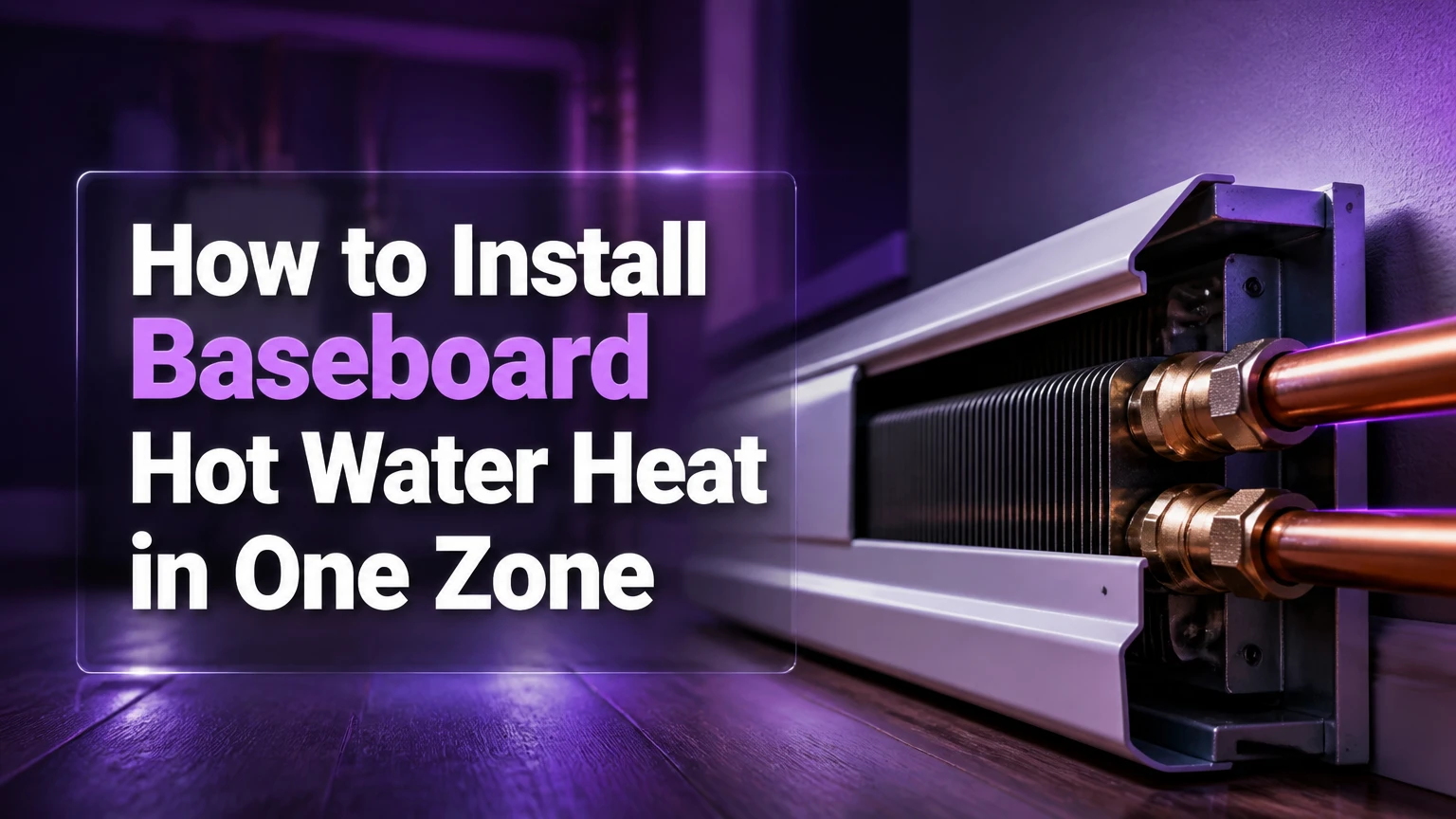
To install baseboard hot water heat, calculate each room’s heat loss, select rated hydronic baseboard, mount the cabinets, connect oxygen-barrier tubing to a properly sized zone, then pressure-test, purge, and balance the circuit. A single-room replacement may take 4-8 hours, but a new boiler zone requires design, permits, controls, and licensed HVAC work.
Key Facts
Standard fin-tube baseboard commonly produces about 500-600 BTU per linear foot at 180°F entering water, but manufacturer ratings vary.
A typical two-story hydronic home has about 12-15 PSI when the system is cold, subject to building height and equipment instructions.
Standard fin-tube circuits often use 3/4-inch copper or oxygen-barrier PEX, while allowable loop length depends on flow and heat loss.
A condensing boiler or air-to-water heat pump may need larger or high-output emitters because 120-140°F water produces less heat than 180°F water.
Baseboard cabinets need unobstructed air movement beneath and through the fin assembly; carpet, drapes, and furniture can reduce output.
Boiler, gas, electrical, combustion, pressure-relief, and code work should be completed or inspected by qualified professionals.
How Does Hydronic Baseboard Heat Work?
Hydronic baseboard heat moves boiler-heated water through a finned metal element, where copper conducts heat to aluminum fins and natural convection warms the room. Cool air enters the lower opening, rises across the fins, and exits through the upper grille without a fan.
A typical circuit contains a heat source, circulator pump, supply piping, baseboard elements, return piping, an expansion tank, air separator, fill assembly, isolation valves, and a pressure-relief valve. A thermostat calls for heat, the control starts the circulator or boiler, and hot water travels through the selected zone.
Baseboard heat is a room emitter, not a complete heating design. The boiler must provide enough output, the circulator must deliver the required flow, and the element must be long enough for the room’s calculated load. A long pipe loop cannot compensate for undersized baseboard or inadequate boiler capacity.
The U.S. Department of Energy describes radiant systems as delivering heat directly to building surfaces or occupied spaces rather than distributing heated air through ductwork. Hydronic baseboard is technically a water-based convection system, so its comfort characteristics differ from electric resistance baseboard and radiant floor heating.
How Much Baseboard Does Each Room Need?
Room-by-room heat loss determines baseboard length; dividing heat loss by 500 BTU per foot is only a preliminary estimate for standard fin-tube at a 180°F design condition. Use Manual J or an equivalent local heat-loss method, then confirm the result with the element manufacturer’s output table.
A simplified planning calculation is:
Required baseboard length = room heat loss in BTU per hour ÷ rated BTU per linear foot
For example, a room with a 7,500 BTU-per-hour design load and baseboard rated at 550 BTU per foot needs approximately 13.6 feet, so the practical selection may be 14 feet. The calculation changes when entering-water temperature, element model, enclosure, or design temperature changes.
| Room heat loss | Element rating | Calculated length | Practical selection |
|---|---|---|---|
| 4,000 BTU/h | 550 BTU/ft | 7.3 ft | 8 ft |
| 6,000 BTU/h | 550 BTU/ft | 10.9 ft | 11 ft |
| 7,500 BTU/h | 550 BTU/ft | 13.6 ft | 14 ft |
| 10,000 BTU/h | 550 BTU/ft | 18.2 ft | 19 ft |
Place baseboard along exterior walls, especially beneath windows, when the room layout permits. The warm upward airflow offsets downdrafts from cold glazing, although modern low-e windows may reduce that need. Do not size from room square footage alone because insulation, window area, air leakage, ceiling height, and local outdoor design temperature alter the result.
What Changes Baseboard Output?
Entering-water temperature, return-water temperature, enclosure design, fin cleanliness, and airflow all change actual output. A fin-tube rating at 180°F water should not be applied unchanged to a 130°F heat-pump circuit.
| Entering water temperature | Typical fin-tube output | Planning consequence |
|---|---|---|
| 180°F | 500-600 BTU/ft | Standard boiler sizing reference |
| 160°F | 400-500 BTU/ft | Often requires additional footage |
| 140°F | 250-400 BTU/ft | Verify exact manufacturer rating |
| 120°F | 150-300 BTU/ft | Conventional baseboard may be inadequate |
These figures are typical planning ranges, not universal ratings. The product’s certified table controls the design.
Which Baseboard Emitter Should You Install?
Standard fin-tube is usually the practical choice for a conventional boiler retrofit, cast iron suits high-mass comfort and durable historic interiors, and low-temperature high-output elements suit condensing boilers or hydronic heat pumps. The best emitter depends on water temperature, available wall length, response time, and budget.
| Emitter type | Typical output basis | Typical material cost | Best application |
|---|---|---|---|
| Standard fin-tube | 500-600 BTU/ft at 180°F | $15-$30/ft | Boiler retrofit |
| Cast iron baseboard | 400-500 BTU/ft at 180°F | $60-$90/ft | High-mass comfort |
| High-output fin-tube | 400+ BTU/ft at lower temperatures | $25-$60/ft | Condensing boiler |
| Fan-assisted hydronic unit | 1,000-4,000+ BTU/unit | $150-$600/unit | Limited wall space |
Cast iron warms more slowly but continues releasing heat after the circulator stops. Standard fin-tube responds faster and weighs much less, making it easier to handle in a renovation.
A conventional fin-tube element is not automatically suitable for a heat pump. If design water temperature is near 120-140°F, calculate the reduced output and consider high-output baseboard, panel radiators, fan convectors, radiant floors, envelope improvements, or a backup heat source.
What Materials and Tools Are Required?
A typical 10-foot fin-tube installation requires one 10-foot element or approved sections, a cabinet, end caps, a damper, mounting screws, tubing, fittings, isolation valves, air-control components, and a thermostat or zone control. New zones also require a circulator or zone valve, branch connections, balancing provisions, and compatible boiler controls.
Materials Checklist
- Rated fin-tube or cast iron element
- Copper tubing or oxygen-barrier PEX-AL-PEX
- Listed transition fittings and support brackets
- Isolation valves and purge valves
- Air separator and automatic vent where the system design requires them
- Thermostat, relay, zone valve, or circulator control
- Plastic guides or approved sleeves at floor and wall penetrations
- Pipe insulation for unheated areas
- Lead-free solder and flux if soldered copper is used
- Pressure gauge, temperature gauge, and approved relief equipment
Tools Checklist
- Tape measure, level, stud finder, and marker
- Tubing cutter, deburring tool, and emery cloth
- Drill with appropriately sized bits
- PEX-AL-PEX press or manufacturer-approved joining tools
- Propane or MAPP torch for soldered copper
- Manifold gauge or boiler pressure gauge
- Hose, bucket, and wrench set for purging
- Vacuum cleaner and soft fin brush for commissioning
Use oxygen-barrier tubing in closed hydronic systems. Ordinary non-barrier PEX can allow oxygen diffusion that accelerates corrosion of ferrous boiler components, pumps, and air separators.
How to Install Baseboard Hot Water Heat
Install the system in eight controlled stages: confirm the design, isolate the existing system, mount the emitter, route tubing, make approved connections, provide expansion clearance, test the circuit, and purge and balance the zone. The most important success factor is correct room-by-room sizing combined with adequate flow.
Before You Start
| Item | Typical single-room value | New-zone implication |
|---|---|---|
| Work time | 4-8 hours | 1-3 days, depending on access |
| Fin-tube material | $150-$400 | $500-$1,500 for zone components |
| Labor | $500-$1,500 | $1,200-$3,500 per zone |
| Baseboard footage | 8-20 ft | Heat-loss calculation required |
| Pipe size | 3/4 inch typical | Hydraulic calculation required |
Turn off electrical power to the boiler and allow hot water to cool. Never open a boiler drain or remove a fitting while the system is hot or pressurized.
Step 1: Calculate the Room Load
Measure the room, windows, doors, exterior walls, insulation, ceiling, and floor exposure. Calculate the design heat loss, select an emitter from its rated table, and record the required flow and water temperature.
Success checkpoint: The selected element has output equal to or greater than the room load at the design entering-water temperature.
Common mistake: Using 500 BTU per foot for a low-temperature system without checking the manufacturer’s rating.
Step 2: Plan the Circuit and Controls
Decide whether the room joins an existing zone or receives a separate zone. Confirm boiler capacity, expansion-tank sizing, circulator head, zone valve or pump control, thermostat location, and supply-return routing before cutting pipe.
A 3/4-inch circuit may carry roughly 1-4 GPM in residential applications, but the required flow follows the heat load:
Flow in GPM = BTU per hour ÷ (500 × design temperature drop)
A 10,000 BTU-per-hour zone with a 20°F temperature drop requires about 1 GPM. Long circuits, multiple rooms, restrictive fittings, and high-output elements may require a hydraulic calculation rather than a footage rule.
Success checkpoint: The designer can identify the supply, return, purge point, isolation points, and control sequence.
Common mistake: Connecting a new zone to an existing loop without confirming pump capacity or boiler control compatibility.
Step 3: Mount the Baseboard Cabinet
Mark the finished-floor height and wall studs. Set the cabinet level, keep its lower opening clear, and fasten the back plate to studs or approved anchors.
Maintain approximately 1 inch above finished flooring when the manufacturer permits that arrangement. Carpet should not block the intake. Follow the product manual because some cabinets specify different clearances.
Leave room for end caps, pipe connections, trim, drapes, and furniture. Do not place a sofa directly against the upper grille.
Success checkpoint: The cabinet is level, secure, unobstructed, and aligned with the planned tubing penetrations.
Common mistake: Mounting the cover tight to thick carpet, which restricts convection and lowers heat delivery.
Step 4: Route the Supply and Return Tubing
Drill clean penetrations through the floor or wall and protect tubing from sharp edges. Use approved sleeves or oversized holes where tubing passes through framing, allowing thermal movement without metal-on-metal contact.
Keep supply and return runs supported according to the tubing manufacturer’s spacing requirements. Insulate pipes in basements, crawlspaces, garages, and other unconditioned spaces to reduce standby loss and prevent condensation or freezing.
Do not bury inaccessible joints unless the fitting system and local code permit them. Keep valves and service connections accessible.
Success checkpoint: Tubing reaches the element without kinks, abrasion, unsupported spans, or concealed unapproved joints.
Common mistake: Drilling through electrical cables, plumbing, or structural framing. Scan first and follow drilling limits for joists and studs.
Step 5: Connect the Element
Cut copper squarely, deburr the interior, clean the outside, apply lead-free flux, and solder only after confirming the joint is dry and properly supported. For PEX-AL-PEX, use the manufacturer’s exact press or compression fittings and calibration procedure.
Use dielectric or approved transition fittings where required by the material combination. Keep plastic and combustible materials away from a torch, and use a fire-resistant shield during soldering.
The copper tube should sit in the element’s support brackets without being clamped so tightly that it cannot expand. Install end caps, dampers, and enclosure parts only after inspecting the element.
Success checkpoint: Every joint is fully seated, visually sound, accessible for inspection, and supported without rigidly trapping the tube.
Common mistake: Heating the solder instead of the fitting. Heat the fitting until solder flows around the joint, then allow it to cool without movement.
Step 6: Allow for Thermal Expansion
Copper expands as water temperature rises. Provide clearance at floor holes, use plastic guides or approved sleeves, and avoid fastening the pipe directly against joists, brackets, or sheet metal.
The often-repeated allowance of 1/16 inch per 10 feet is not a universal installation specification. Actual movement depends on temperature change, pipe length, material, and restraint, so the product manual and local plumbing code control.
Success checkpoint: The tube can move slightly at penetrations and does not scrape bare metal when warmed.
Common mistake: Packing a floor hole tightly with wood or rigid sealant. That installation commonly produces ticking and knocking.
Step 7: Pressure-Test the Circuit
Test before closing walls or floors. Isolate the boiler, expansion tank, relief valve, gauges, and other components if the test pressure could exceed their ratings, then test the new piping using the pressure and method required by local code and the fitting manufacturer.
A cold residential hydronic system commonly operates around 12-15 PSI, but a test pressure of 25 PSI is not automatically safe for every component or jurisdiction. Never exceed the lowest-rated component, and never use compressed air when the fitting manufacturer or local code prohibits it.
Inspect every joint, valve, connection, and transition. A dry paper towel around each joint can reveal a slow seep.
Success checkpoint: The circuit holds the specified test pressure for the required period with no visible leakage or measurable unexplained loss.
Common mistake: Testing an entire boiler assembly at a pressure intended only for new piping.
Step 8: Fill, Purge, Balance, and Commission
Fill the zone slowly, open the purge path, and remove air until water flows steadily without sputtering. Restore the system to its required cold pressure, open isolation valves, power the controls, and run the zone through a complete heating cycle.
A baseboard element may have no separate bleeder valve. In that design, purge air through the zone purge station or an approved high-point air vent. Do not assume opening a small vent on the cabinet will remove every air pocket.
Measure supply and return temperatures after the system stabilizes. Confirm thermostat operation, circulator direction, zone-valve movement, boiler response, relief discharge routing, and adequate heat at the far end of the circuit.
Success checkpoint: The zone heats evenly, the boiler reaches its operating sequence, pressure remains stable, and no air or water noise occurs.
Common mistake: Leaving a closed isolation valve or failing to purge the high point, which causes a cold element despite a running boiler.
What Are the Correct System Specifications?
Residential hydronic systems commonly use 180°F design water with a 20°F temperature drop, 12-15 PSI cold pressure, and 3/4-inch distribution piping, but these are design references rather than universal installation requirements. High-efficiency boilers and heat pumps often operate at lower temperatures and need different emitters.
| Design item | Conventional reference | Low-temperature design |
|---|---|---|
| Supply-water target | 180°F | 120-140°F |
| Typical design drop | 20°F | 10-20°F |
| Cold pressure | 12-15 PSI | 12-15 PSI, building dependent |
| Typical circuit flow | 1-4 GPM | Calculation required |
| Common emitter | Standard fin-tube | High-output element or radiator |
A two-story house may require more than 12 PSI if the boiler is substantially above the expansion tank. The static pressure must exceed the elevation head and maintain positive pressure at the highest emitter.
The 60-70-foot loop limit is also a rule of thumb, not a code threshold. A circuit with 40 feet of baseboard may fail if its pump cannot deliver flow, while a properly designed circuit can sometimes exceed a simple footage limit. Temperature drop, pipe resistance, fittings, emitter distribution, and available pump head decide the result.
What Does Installation Cost and How Long Does It Take?
A single-room fin-tube replacement typically costs $150-$400 in materials and takes 4-8 hours when accessible connections already exist. A new hydronic zone commonly costs $1,200-$3,500 installed, with permits, boiler capacity, concealed piping, controls, and finish repairs causing the largest variations.
| Project scope | Typical time | Typical installed cost | Main cost variable |
|---|---|---|---|
| Cover and element replacement | 2-4 hours | $150-$600 | Element length |
| Single-room connection | 4-8 hours | $500-$1,500 | Access to existing loop |
| New basement-accessible zone | 1-2 days | $1,200-$2,500 | Controls and branch piping |
| Multi-zone renovation | 2-4 days | $3,000-$8,000+ | Boiler and finish work |
These are typical North American planning ranges, not bids. Copper prices, regional labor rates, asbestos abatement, drywall repair, and electrical work can move the final price substantially.
What Are the Main Alternatives?
Hydronic baseboard is often quieter than forced air and avoids fan-driven dust circulation, but ducted heat responds faster and can provide cooling. Radiant floors improve surface comfort but usually cost more to retrofit because flooring and subfloor construction are involved.
| System | Typical water or air condition | Response | Retrofit disruption |
|---|---|---|---|
| Fin-tube baseboard | 160-180°F water | Fast for hydronic | Low to moderate |
| Cast iron baseboard | 160-180°F water | Slow, high retention | Moderate |
| Radiant floor | 85-130°F water | Slow, even | High |
| Ducted heat pump | 90-120°F supply air | Fast | Moderate to high |
| Mini-split heat pump | Variable refrigerant | Fast | Low to moderate |
Baseboard is a poor choice where every exterior wall is needed for furniture, where cooling must use the same distribution system, or where low-temperature heat cannot deliver the room load. It remains practical for boiler replacements, perimeter rooms, and homes with accessible basement piping.
What Common Problems Occur After Installation?
Most new-system failures come from incorrect sizing, trapped air, inadequate flow, restricted airflow, or expansion noise. Diagnosing the symptom across the entire zone is more reliable than replacing a thermostat or element immediately.
| Symptom | Likely cause | Corrective action |
|---|---|---|
| Entire element stays cold | Closed valve, air lock, failed control | Confirm call for heat, valves, pump, and purge |
| First room hot, last room cold | Excessive circuit resistance or low flow | Calculate flow and rebalance or redesign |
| Top grille warm, room cold | Dirty fins or blocked airflow | Vacuum fins and clear furniture or drapes |
| Ticking during warm-up | Tight hole or rigid support | Add sleeve, guide, or clearance |
| Pressure falls repeatedly | Leak, relief discharge, or expansion issue | Inspect, repair, and verify tank and relief valve |
| Boiler runs, zone remains cold | Zone valve, relay, or circulator fault | Test control voltage and pump operation |
Vacuum aluminum fins gently because bent fins reduce airflow. Replace severely corroded elements rather than masking the problem with a new cover.
Do not repeatedly add water to a system that loses pressure. Frequent makeup water introduces oxygen and can indicate a leak, failed expansion tank, relief-valve discharge, or defective automatic fill assembly.
What Safety and Code Limits Matter?
A new boiler, gas train, venting system, electrical circuit, pressure-relief assembly, or combustion adjustment should be handled by licensed professionals under local code. Hydronic tubing alone does not make the project a simple plumbing repair when the work changes a fuel-burning appliance or life-safety control.
Stop and obtain professional help when:
- The boiler has gas, oil, or solid-fuel combustion equipment.
- The work requires changing flue, vent, combustion, or electrical wiring.
- The system contains asbestos insulation or unknown legacy materials.
- The new zone could exceed boiler output or expansion-tank capacity.
- A relief valve discharges, pressure rises sharply, or water approaches boiling temperature.
- Piping is concealed without a code-approved, accessible connection method.
- The building is in a freeze-prone location without a reliable low-temperature strategy.
Install a carbon-monoxide alarm outside sleeping areas and follow the boiler manufacturer’s instructions. Never disable a pressure-relief valve, bypass a high-limit control, or cap a discharge pipe.
How Do You Choose Between DIY and Professional Installation?
A homeowner may reasonably replace an accessible cabinet or element when the existing piping, controls, and boiler remain unchanged, but a new zone should receive professional design and inspection. The dividing line is not soldering skill alone; it is whether the work changes pressure, combustion, electrical controls, or system hydraulics.
A practical DIY scope includes measuring, mounting cabinets, cleaning fins, installing approved covers, and preparing accessible tubing routes. A professional scope includes heat-loss design, pump selection, zone control, boiler integration, pressure testing, purge setup, permits, and commissioning.
The installer should provide the heat-loss result, emitter output, design supply and return temperatures, flow requirement, pressure-test record, control sequence, and operating instructions. Those documents make future troubleshooting substantially easier.
Frequently Asked Questions
Can I Add Baseboard Heat to an Existing Boiler?
Yes, if the boiler has sufficient output and the existing system can accommodate the new zone hydraulically. The addition may require a zone valve, circulator, relay, expansion-tank review, purge station, and properly sized branch piping. A tee connection alone does not create a balanced or controllable heating zone.
Is PEX Safe for Hot Water Baseboard?
Oxygen-barrier PEX or PEX-AL-PEX can be suitable for closed hydronic heating when the product is rated for the system temperature and pressure. Ordinary plumbing PEX may permit oxygen diffusion and should not automatically replace barrier tubing. Use the manufacturer’s fittings, support spacing, bend limits, and concealed-joint rules.
Should Baseboard Go on Interior or Exterior Walls?
Exterior walls, especially beneath windows, are the usual locations because the emitter offsets cold downdrafts and perimeter heat loss. Interior-wall placement can work when room geometry or furniture requires it, but the heat-loss calculation and airflow clearance remain more important than wall location alone.
Why Does the Last Baseboard in a Loop Stay Cold?
The final element may be cold because air blocks flow, a valve is closed, the circulator lacks head, the loop has excessive resistance, or earlier emitters remove too much heat. Verify valve position and purge the circuit first, then measure supply and return temperatures and check the calculated flow.
Can Baseboard Heat Work With an Air-to-Water Heat Pump?
Yes, but conventional baseboard may be undersized at heat-pump water temperatures around 120-140°F. Compare the room load with the emitter’s low-temperature output, then add footage or use high-output baseboard, fan convectors, panel radiators, or radiant floors where necessary.
How Much Clearance Does Baseboard Need?
Keep the lower intake and upper outlet unobstructed, avoid thick carpet covering the intake, and keep furniture and drapes away from the cabinet. Exact clearances vary by product, so the installation manual controls. A blocked cabinet can reduce convection enough to leave a correctly sized room cold.
The Bottom Line
How to install baseboard hot water heat correctly depends on four linked decisions: room heat loss, emitter output at the actual water temperature, circuit hydraulics, and safe commissioning. Standard fin-tube works well for many boiler systems, while low-temperature emitters are usually necessary for heat pumps. Mount the cabinets level, protect tubing from abrasion, allow thermal movement, test within component limits, purge every circuit, and verify the finished zone under load.