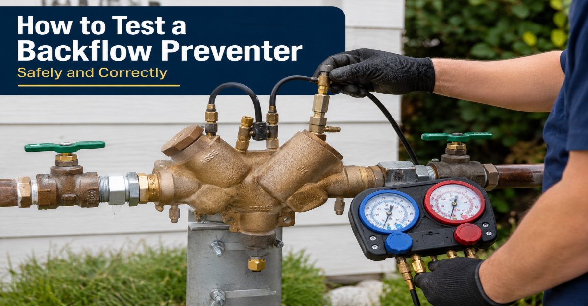
To test a backflow preventer, identify the assembly, connect a calibrated differential-pressure gauge to its test cocks, purge air, isolate flow, and measure each check valve and relief function against the manufacturer’s and local authority’s criteria. A trained tester usually completes one assembly in 20-45 minutes and documents every reading.
Key Facts at a Glance
An RPZ test checks first-check holding pressure, relief-valve opening pressure, and second-check tightness.
The common USC 10th Edition RPZ benchmarks are 5.0 psid minimum for the first check and 2.0 psid minimum relief-valve opening.
A PVB protects against backsiphonage, but a standard PVB cannot protect against backpressure.
Test-cock numbering and acceptable readings vary by manufacturer, assembly model, and local water authority.
A homeowner can inspect for leaks, but many jurisdictions require an approved or certified tester to submit official results.
A failed test indicates a protection problem, not automatically a defective check valve, because shutoff-valve leakage and trapped air can distort readings.
What Does a Backflow Preventer Protect Against?
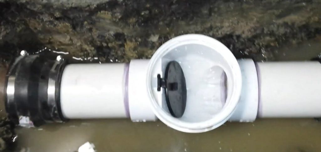
A backflow preventer protects potable water by forcing water to move in one direction and interrupting a reverse-flow connection. The U.S. Environmental Protection Agency’s Cross-Connection Control Manual describes backflow as “the undesirable reversal of flow of water or other substances through a cross-connection into the public water system.”
A cross-connection may link drinking water with irrigation, boiler chemicals, fire-protection additives, hose bibs, medical equipment, or process piping. Backflow occurs through either backsiphonage or backpressure:
- Backsiphonage: A supply-main pressure drop creates negative pressure that pulls downstream water backward.
- Backpressure: Downstream pressure exceeds supply pressure because of pumps, elevated tanks, boilers, or compressed systems.
The hazard determines the assembly. A lawn irrigation system may contain fertilizer or pesticide residue, while a commercial process line may contain toxic chemicals. A device suitable for a low-hazard connection is not automatically suitable for a high-hazard connection.
Why does a backflow preventer need a field test?
A backflow preventer needs a field test because springs, elastomeric seals, check discs, and relief mechanisms can degrade while the exterior remains intact. A visual inspection can find corrosion or discharge, but it cannot prove that a check valve holds under differential pressure.
Field testing also exposes installation problems. A blocked relief drain, buried assembly, undersized discharge pipe, frozen body, or leaking isolation valve can compromise protection even when internal components are serviceable.
Which Backflow Preventer Do You Have?
The assembly type determines the test method and the hazard protection available. Read the body label before connecting a gauge, then confirm the model’s installation and test instructions because test-cock positions are not universal.
| Assembly | Internal arrangement | Protects against | Cannot reliably protect against | Typical applications |
|---|---|---|---|---|
| RPZ | Two check valves plus pressure-relief valve | Backsiphonage and backpressure | Poor drainage or freezing conditions | Chemical systems, hospitals, commercial irrigation |
| DCVA | Two independently spring-loaded check valves | Backsiphonage and limited backpressure | High-hazard toxic substances | Fire lines, low-hazard irrigation, mechanical systems |
| PVB | Spring check valve plus air-inlet valve | Backsiphonage | Continuous backpressure | Lawn irrigation, hose and atmospheric zones |
| SVB | Atmospheric vacuum breaker with float or air inlet | Backsiphonage under intermittent use | Backpressure and continuous pressure | Some hose-connected fixtures and irrigation zones |
An RPZ, also called an RPB or reduced-pressure principle assembly, normally has four test cocks and a relief valve between the checks. A DCVA usually has four test cocks but no relief port. A PVB has an air-inlet structure and must be installed above downstream outlets according to its listing.
Do not identify a device by shape alone. A pressure vacuum breaker and a reduced-pressure assembly can both have a spring check, but their permitted hydraulic conditions differ substantially.
What Tools and Prerequisites Are Required?
A professional test requires a calibrated differential-pressure gauge kit, correct test-cock adapters, bleed hoses, manufacturer instructions, and a safe way to isolate and drain the assembly. Typical equipment includes a three-valve or five-valve gauge, SAE adapters, hose plugs, absorbent material, a flashlight, replacement caps, and a reporting form.
| Item | Typical specification | Purpose | Field caution |
|---|---|---|---|
| Differential gauge | 0-15 or 0-30 psid range | Measures pressure difference | Verify current calibration certificate |
| Test-cock adapters | Correct SAE or model-specific size | Connects hoses without damaging ports | Hand-tighten into plastic test cocks |
| Bleed hoses | 3-6 feet, rated for potable water | Removes air and directs discharge | Keep hose ends below the gauge |
| Isolation valves | Upstream and downstream shutoffs | Establishes static test conditions | Confirm each valve actually closes |
| Test record | Model, serial, readings, date | Creates compliance evidence | Use the authority’s current form |
The gauge should have current calibration under the requirements of the local water authority. Annual calibration is common, but some programs specify a different interval or approved laboratory. A gauge that reads accurately in the shop can still produce unstable results if air remains trapped in the hoses.
Safety checks before connecting the gauge
Confirm that the assembly is accessible, supported, protected from traffic, and connected to a functioning drain. An RPZ relief valve may discharge several gallons during testing, and discharge water can flood a mechanical room or create a slip hazard.
Do not test a contaminated process connection without following the site’s lockout, hygiene, and water-quality procedures. Wear eye protection and gloves, especially where the assembly protects against chemicals, sewage, boiler additives, or reclaimed water.
How to Test a Backflow Preventer: RPZ Procedure
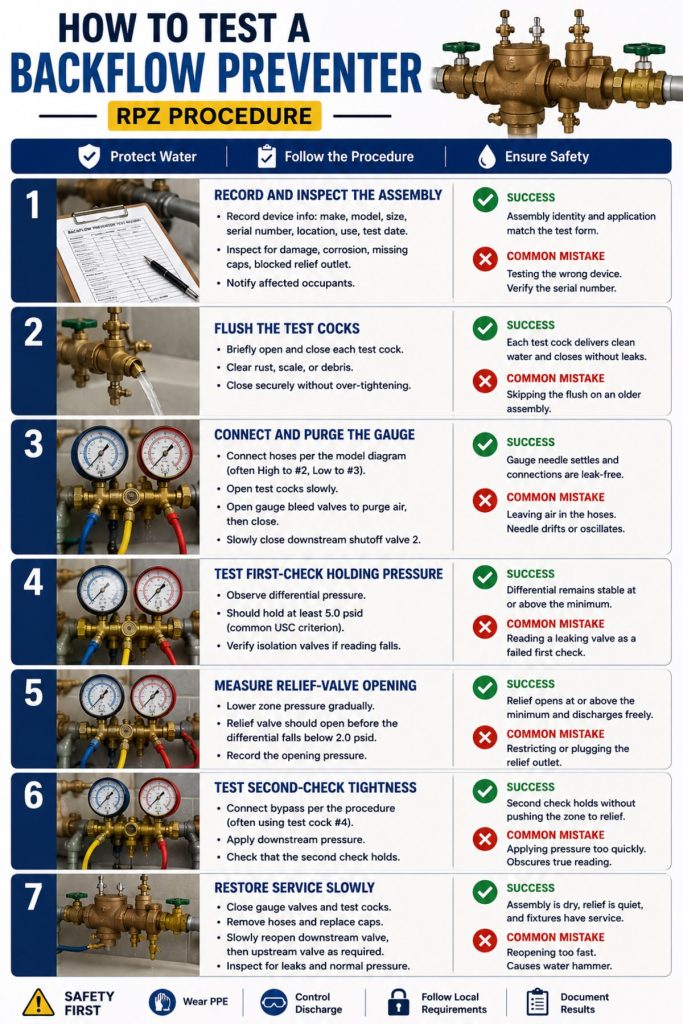
Testing an RPZ assembly normally takes six stages: record the device, flush the test cocks, connect and bleed the gauge, test the first check, test relief opening, and test the second check. The common USC Foundation 10th Edition criteria are 5.0 psid minimum first-check pressure and relief opening before the zone falls below 2.0 psid, but the adopted local rule controls certification.
Step 1: Record and inspect the assembly
Record the manufacturer, model, nominal size, serial number, location, water-service use, and test date. Check the body for cracks, corrosion, freezing damage, unauthorized modifications, blocked relief discharge, and missing test-cock caps.
Notify affected occupants before closing the water supply. Commercial sites may need coordination with fire protection, production, medical equipment, irrigation controls, or building management.
Success checkpoint: The assembly identity and application match the test form and the authority’s device inventory.
Common mistake: Testing the wrong device because two assemblies serve adjacent branches. Trace the piping and verify the serial number.
Step 2: Flush the test cocks
Briefly open and close each test cock to clear rust, scale, or grit from the port. Do not hold a test cock open long enough to create uncontrolled discharge, and do not use excessive force on small brass or plastic fittings.
Flushing matters because debris can enter the gauge manifold and damage needle valves or diaphragms. It also prevents a blocked test cock from being mistaken for a failed internal check.
Success checkpoint: Each test cock delivers clean water and closes without continuing leakage.
Common mistake: Skipping the flush on an older assembly with visible mineral deposits. A small particle can hold a check disc off its seat during the test.
Step 3: Connect and purge the gauge
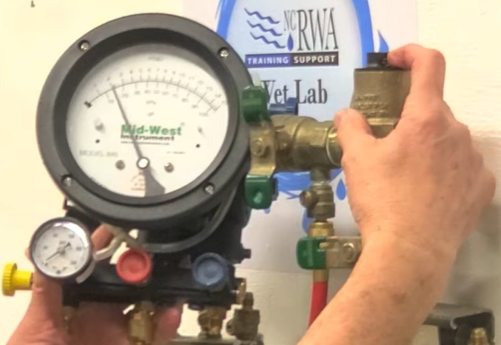
Follow the model-specific diagram rather than relying only on hose color. On many RPZ procedures, the high hose connects to test cock 2 and the low hose connects to test cock 3, while the bypass hose is used later at test cock 4.
Open the selected test cocks slowly. Open the gauge bleed valves until water flows without bubbles, then close the bleed valves. Establish the required static condition by slowly closing the downstream shutoff valve, commonly identified as shutoff valve 2.
Success checkpoint: The gauge needle settles instead of oscillating, and no hose connection leaks.
Common mistake: Leaving air in a hose. Trapped air compresses and expands, producing a drifting or unstable differential reading.
Step 4: Test first-check holding pressure
Observe the differential pressure between the supply side and the reduced-pressure zone. The first check should hold at least 5.0 psid under the commonly used USC RPZ test criterion.
A steadily falling reading indicates leakage through the first check, but a leaking downstream shutoff valve can create the same symptom. Confirm the isolation valves before condemning the check assembly.
Success checkpoint: The differential remains stable at or above the applicable minimum for the specified observation period.
Common mistake: Treating a momentary needle movement as a failure. Record the stabilized value and follow the jurisdiction’s observation rule.
Step 5: Measure relief-valve opening
Use the gauge manifold to lower the pressure in the reduced-pressure zone gradually. The relief valve should open before the zone differential falls below 2.0 psid under the common USC criterion.
Record the opening pressure, not merely the pressure after water begins spraying. A relief valve that opens at 1.5 psid may discharge visibly yet fail the 2.0 psid requirement.
Success checkpoint: The relief valve opens at or above the applicable minimum and discharges through a clear path.
Common mistake: Restricting or plugging the relief outlet during testing. The outlet must remain able to discharge safely.
Step 6: Test second-check tightness
Connect the bypass arrangement specified by the gauge manufacturer and assembly procedure, often using test cock 4. Apply downstream pressure to challenge the second check while observing the gauge.
The second check should prevent reverse movement and maintain the required separation from the relief opening condition. A falling reading suggests second-check leakage, although incorrect hose sequencing or a leaking isolation valve can produce misleading results.
Success checkpoint: The second check holds against the prescribed backpressure challenge without pushing the zone toward relief opening.
Common mistake: Applying pressure too quickly. Sudden pressure changes can create water hammer and obscure the actual holding behavior.
Step 7: Restore service slowly
Close the gauge valves and test cocks in the prescribed order, remove the hoses, replace test-cock caps, and slowly reopen the downstream shutoff valve. Open the upstream valve as required by the manufacturer’s restoration sequence, then inspect the relief port and all connections for leaks.
Slow reopening limits water hammer, which can damage piping, gauges, valves, and downstream equipment. Confirm that pressure returns to normal and that the relief valve stops discharging.
Success checkpoint: The assembly is dry at the connections, the relief port is inactive, and downstream fixtures regain service.
What Readings Indicate an RPZ Pass?
An RPZ passes only when every required function meets the adopted test standard, not when one pressure reading looks acceptable. Under the commonly referenced USC 10th Edition procedure, the first check holds at 5.0 psid or higher, the relief valve opens at 2.0 psid or higher, and the second check remains tight under backpressure.
| Test function | Common RPZ criterion | Failure indication | Likely investigation |
|---|---|---|---|
| First check | At least 5.0 psid | Differential falls steadily | Debris, worn disc, leaking shutoff |
| Relief valve | Opens at or above 2.0 psid | Opens below 2.0 psid | Damaged spring, fouling, worn seat |
| Second check | Holds under challenge | Differential decays | Debris, damaged check, bypass error |
| Relief drainage | Clear discharge path | Flooding or restricted flow | Blocked drain, undersized piping, freezing |
These values are not universal pass numbers for every jurisdiction or device. The manufacturer’s listing, state plumbing code, water purveyor rules, and adopted test form may impose different criteria. A certified tester should resolve conflicts before submitting a pass result.
How Is a DCVA Tested?
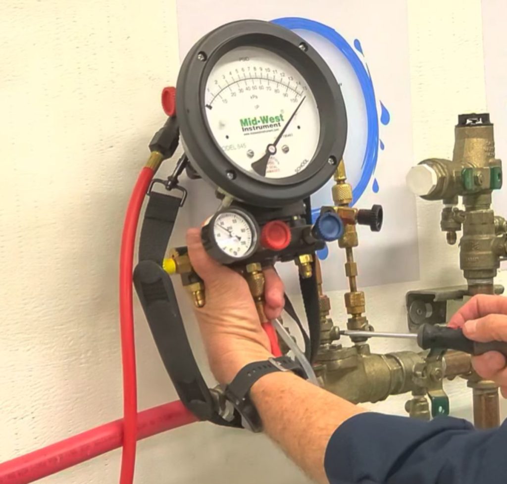
A DCVA is tested with a differential gauge by measuring first-check holding pressure, second-check holding pressure, and the behavior of the assembly under the authority’s specified flow or pressure condition. A DCVA has no intermediate relief valve, so an RPZ relief-opening procedure does not apply.
The tester generally flushes the test cocks, connects the high and low hoses according to the model diagram, purges air, and isolates the downstream side. The first check is challenged and observed for stable pressure, then the second check is tested against backpressure or the prescribed differential condition.
| DCVA test focus | What the tester observes | Common defect |
|---|---|---|
| First check | Stable upstream-to-zone differential | Debris on check seat |
| Second check | Stable downstream challenge | Spring fatigue or scale |
| Shutoff integrity | Isolation during static test | Valve passing internally |
| Installation condition | Orientation, access, drainage | Buried or unsupported assembly |
DCVA readings and minimums vary more visibly across jurisdictions than the familiar RPZ values. Never apply the 5.0 psid and 2.0 psid RPZ thresholds to a DCVA without a governing procedure that specifically authorizes them.
How Is a PVB Tested?
A PVB test checks the spring-loaded check valve and air-inlet valve, with special attention to the point at which the air inlet opens as pressure falls. A PVB must be installed above downstream outlets and cannot be used where continuous downstream backpressure can exist.
The tester isolates the assembly, attaches the correct gauge or test kit, purges air, and lowers inlet pressure under the manufacturer’s procedure. The check valve must prevent reverse flow, and the air inlet must open at the listed pressure before backsiphonage can continue.
| PVB condition | Required design fact | Failure consequence |
|---|---|---|
| Installation height | Above downstream outlets | Siphon protection may be lost |
| Pressure exposure | No continuous backpressure | Reverse flow can bypass protection |
| Check valve | Closes against reverse flow | Contaminated water can migrate |
| Air inlet | Opens at listed pressure | Vacuum is not relieved |
A PVB that drips intermittently may be responding to pressure fluctuations, but continuous leakage can indicate a fouled check, damaged seal, or defective air-inlet valve. Do not cap the air inlet to stop a nuisance discharge.
Why Do Backflow Preventers Fail Tests?
Backflow preventers usually fail because debris prevents a check from seating, springs lose force, seals deteriorate, or freezing damages internal parts. Test errors also matter: trapped air, leaking isolation valves, incorrect hose connections, and wrong device identification can imitate component failure.
| Symptom | Probable cause | Correct response |
|---|---|---|
| First-check reading declines | Debris or passing shutoff valve | Verify isolation, flush, then retest |
| Relief opens below criterion | Fouled relief seat or weak spring | Repair with listed parts and retest |
| Gauge fluctuates | Trapped air or unstable supply | Bleed hoses and repeat static setup |
| Test cock sprays at adapter | Cross-threading or overtightening | Stop, inspect threads, replace damaged port |
| Relief valve drips after test | Debris on relief seat | Flush according to instructions, then repair |
| Body cracked after winter | Freeze damage | Isolate and replace damaged assembly |
Mineral scale is especially common in hard-water regions. Scale can increase friction around a poppet and prevent full closure even when the spring still has adequate force.
A counterintuitive field rule is that a failed first check does not prove the check valve failed. A downstream shutoff valve that passes water can prevent a stable test boundary, so valve isolation is part of diagnosis rather than a separate administrative step.
What Should You Do After a Failed Test?
After a failed test, record the exact failing function, isolate the hazard if necessary, repair with manufacturer-approved parts, and perform a complete retest. Replacing only the visibly damaged rubber disc can leave a weak spring, obstructed relief passage, or damaged seat unresolved.
Use this decision sequence:
- Confirm the device: Match manufacturer, model, size, and flow direction.
- Confirm the setup: Check hose positions, gauge valves, bleed procedure, and test-cock operation.
- Verify isolation: Test whether upstream and downstream shutoffs hold.
- Flush and retest: Remove loose debris only by the approved procedure.
- Repair or replace: Use a listed rebuild kit that matches the assembly.
- Document the result: Submit the official report if local rules require it.
- Escalate the hazard: Provide temporary protection or restrict service where contamination risk remains.
A rebuild is often appropriate when the body is intact and replacement parts are available. Replacement is generally preferable when the body is cracked, severely corroded, repeatedly fails after rebuilding, lacks parts support, or no longer matches the hazard classification.
How Often Should Testing Occur?
Annual testing is common for commercial backflow assemblies, but the legally required interval depends on the state, municipality, water purveyor, assembly type, and risk category. Fire-protection systems, high-hazard connections, and sites with repeated failures may receive additional inspection or testing requirements.
Property owners should maintain:
- Device model, size, serial number, and location
- Installation and replacement dates
- Tester name, certification number, and company
- Gauge serial number and calibration date
- Individual differential readings
- Repairs, parts, retests, and submission confirmations
Monthly owner inspections can identify active dripping, corrosion, blocked drains, frost exposure, missing caps, and unauthorized alterations. Monthly inspection does not replace the formal performance test.
Who Should Perform and Certify the Test?
A certified backflow tester should perform and certify an official test because most water authorities restrict compliance reporting to testers holding a recognized credential, such as an ASSE tester certification or a jurisdiction-approved equivalent. Exact credential names and renewal rules vary.
A homeowner can inspect an exposed assembly and may perform non-certifying troubleshooting where local rules allow, but a gauge reading is not the same as a legal certification. The tester must know the adopted procedure, use calibrated equipment, and submit the result through the authority’s reporting system.
Commercial sites should select a tester familiar with RPZ, DCVA, PVB, fire-service, irrigation, and high-hazard installations. A low-cost test that omits serial-number verification, individual readings, or a retest can create compliance problems later.
How Long Does Testing Take and What Does It Cost?
A routine backflow test typically takes 20-45 minutes per accessible assembly. Typical residential and light-commercial testing costs range from $75-$200, while repairs, difficult access, traffic control, freeze damage, and high-hazard procedures increase the total.
| Service or component | Typical range | Main cost driver | Expected duration |
|---|---|---|---|
| Routine single-device test | $75-$200 | Local labor and reporting | 20-45 minutes |
| Gauge calibration | $100-$180 | Laboratory and shipping | Several days |
| RPZ rebuild kit | $40-$350 | Size, brand, and valve design | Parts-dependent |
| Standard rebuild labor | $150-$500 typical | Access and scale | 1-2 hours |
| Full assembly replacement | $250-$1,000+ typical | Size, material, installation | 2-6 hours |
These are typical market ranges, not regulated prices. A buried DCVA may cost more to access than an exposed RPZ, while an indoor RPZ may require drainage work before the test can proceed safely.
Common Testing Mistakes and How to Fix Them
Air left in the hoses: The needle fluctuates or slowly drifts. Bleed each hose until bubble-free water flows, close the bleed valves, and repeat the test.
Leaking downstream shutoff valve: The first-check result declines even though the check appears clean. Verify valve tightness and use the approved compensating or isolation method before diagnosing the internal check.
Wrong test-cock sequence: The gauge shows implausible pressure or relief water discharges unexpectedly. Stop, compare the model diagram with the procedure, and reconnect only after identifying the high, low, and bypass points.
Overtightened adapter: A plastic or small brass test cock leaks around the fitting. Remove the adapter, inspect threads, replace damaged components, and hand-tighten the correct adapter.
Blocked relief drain: The assembly passes mechanically but discharge floods the room. Clear or redesign the drain according to code; never obstruct the relief outlet.
Testing a PVB for backpressure protection: A PVB cannot substitute for an assembly rated for continuous backpressure. Replace or redesign the protection when pumps, elevated tanks, or pressurized downstream equipment can reverse the pressure relationship.
FAQ
Can I test a backflow preventer without a gauge?
You can inspect a backflow preventer for corrosion, frost damage, discharge, missing caps, and blocked drainage without a gauge. You cannot prove check-valve tightness or relief-opening pressure by looking at the body or observing normal water flow. A calibrated differential-pressure test kit is required for a meaningful performance test.
What does water dripping from an RPZ mean?
Water dripping from an RPZ relief port may indicate debris on the relief seat, a failed check valve, pressure fluctuation, freezing damage, or normal discharge during a pressure event. Continuous dripping requires diagnosis because it can waste water and indicate reduced separation. Keep the drain open and arrange a qualified test.
Can a failed backflow preventer contaminate drinking water immediately?
A failed backflow preventer creates a loss of verified protection, but contamination occurs only if a cross-connection and reverse-flow condition are also present. Treat the failure seriously by isolating the hazard, notifying the responsible water or facility authority when required, and correcting the assembly before service continues.
Is an RPZ safer than a DCVA?
An RPZ provides higher protection because its intermediate relief valve can discharge when the reduced-pressure zone approaches the supply pressure. A DCVA lacks that relief mechanism and is normally limited to low-hazard applications. The RPZ also needs drainage, more maintenance, and protection from freezing because it intentionally discharges during certain failures.
How do I find the correct test procedure for my model?
Read the manufacturer, model, size, flow-arrow, and listing information stamped on the body or identification tag. Then use the current manufacturer test sheet and the local water authority’s adopted standard. If the body label is missing or illegible, have a qualified tester identify the assembly before connecting a gauge.
The Bottom Line
To test a backflow preventer correctly, identify the device, use a calibrated gauge and correct adapters, purge all air, verify isolation valves, test each required function, restore water slowly, and document the readings. For an RPZ, the commonly used USC benchmarks are 5.0 psid for first-check holding and 2.0 psid for relief opening, but local requirements control the official result. Include how to test backflow preventer procedures in a certified testing program rather than relying on visual inspection alone.